Massimo Altieri
Flight Simulation Site
Home Cockpit building report
The dream begins... page 1
The 737 project page 2
The 737 project page 3
The 737 project page 4
The 737 project page 5
The 737 project page 6
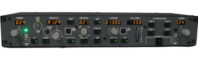
OpenCockpits MCP V3
CRGSim suite
MIP panels
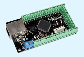
Polabs POKEYS 57E

Polabs POKEYS 57E
BOEING 737 Home cockpit construction history - page 5
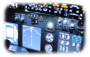
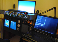
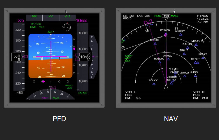
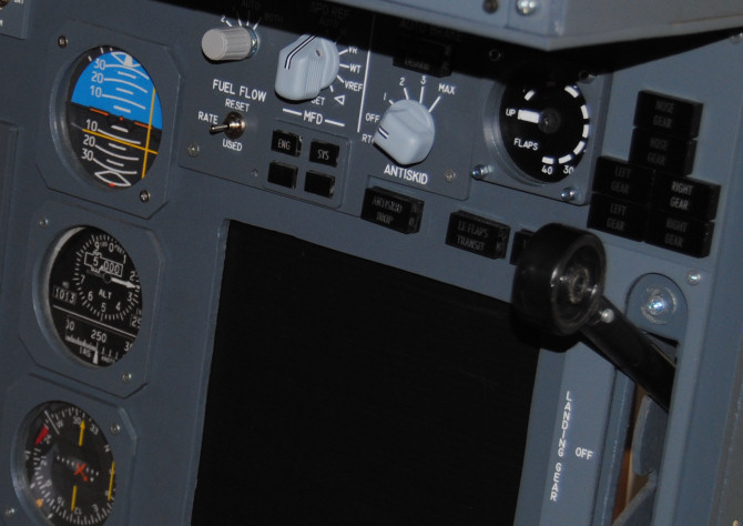
Activating the MIP - first display monitor.
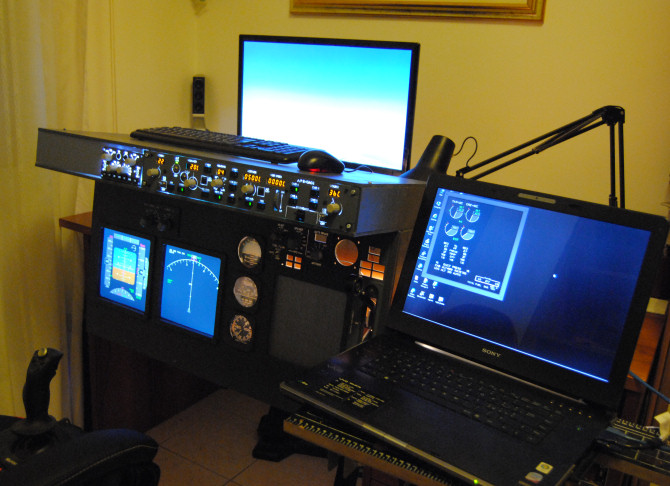
It was not so easy to find the monitors for my glass cockpit displays; it is easier to find a 19" than a 17", and is nowadays very difficult to find a good 15", but you need small monitors for this. Finally I bought a 17" from Amazon, and it fitted quite well, even if I had to cut out the left side wall to position the monitor in front of the 2 holes, leaving enough space for the secondary monitor (standby gauges and EICAS), that I am still looking for.
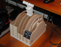
I am feeling that the panel is getting something serious by now. In the picture below you can see the panel in natural light, I have not yet installed the backlighting, that I am planning to make using flexible LED strips (12V) positioned behind the engraved panels. OC MCP and EFIS come already backlighted.

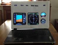
In order to fit the monitor in the narrow space behind the panel, it is necessary to remove the plastic frame around the screen. It is possible using a thin screwdriver and acting progressively all around the frame. Removing the frame allows to save some millimeters, otherwise the primary monitor will overlap with the standby gauges, that must be under the secondary monitor.
Over the holes for NAV and PFD displays I mounted 2 frames bought from Hispapanels, so that they looks like 2 different monitors; in any case the frames are needed to reproduce the real B737 MIP and protect the monitor behind.
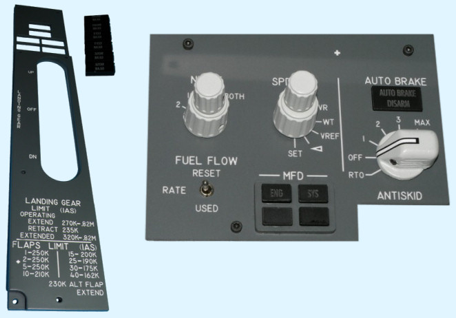
On the right of the panel is visible the landing gear lever. This part requires a dedicated chapter, because it is quite difficult to obtain a good "feel" using a home made mechanism. I made it by a plastic tube sliding over an aluminium core, with a spring inside that connects the two elements. On the net there are many examples of the gear lever mechanism, and many companies sell the complete thing already mounted and ready to use (guess what ? it costs about 150-200 euros or even more) but I am quite happy with mine (and I spent about 10 euros including 2 microswitches).
I enclose here a drawing of the lever that I built, it is just a draft, sizes are not accurate.
Time to build another part of the main instrument panel : the 737 flaps gauge!
I bought the parts from Hispapanels, and they sent me the frames, the transparent cover, the scale, 2 needles. I also bought the components offered to completion of the kit : the servo motor (Hitec HS-311 or Futaba S3003) and a mix of gears and shafts.
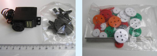
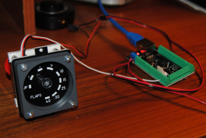
I cut 4 cylinders from an aluminium profile tube and put 4 screws inside in order to create a structure for the gauge. In the center of a square plastic board I drilled the hole for the shaft, and monted the gears and the needles. The activation is quite simple : red and black wires must be connected to +5V and ground, and the white wire goes into one of the pins of the POKEYS available for servo control.
In FSSymphony I configured that pin as a PWM (Pulse Width Management) SERVO control; FSSymphony offers a section dedicated to 737 specific controls, and that includes a flap gauge calibration utility. Using this you can set the angle for each position of the flaps corresponding to different positions of the flaps lever.
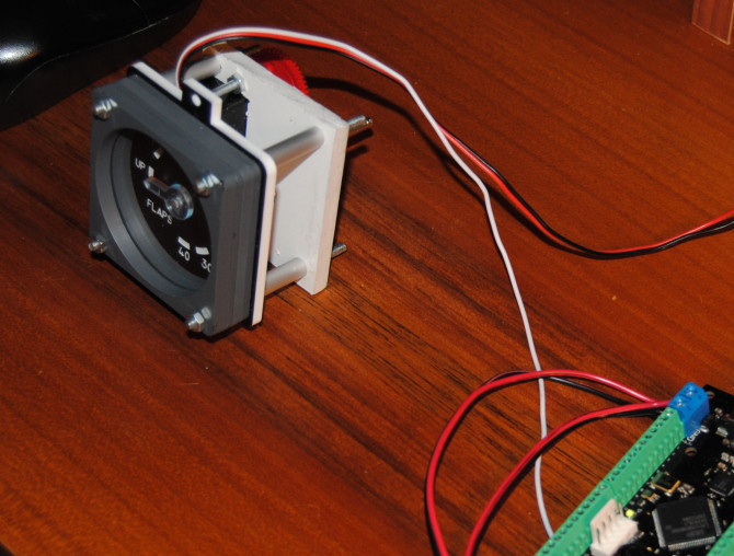
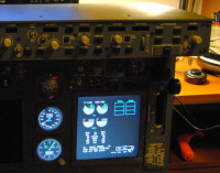
And this is how the new-build flaps gauge looks like after I installed it on the panel :
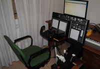
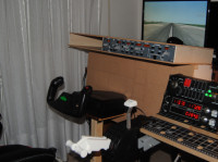
The standby gauges and the EICAS monitor are fake, just cardboards with printed graphics. I definitively need a 15" LCD monitor! But it took me a lot of time searching on the net before I found a Fujitsu Siemens Scencview B15 for only 30 euros on EBay.
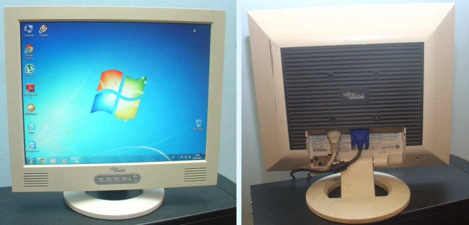
The monitor arrived just a few days after order, in good conditions and perfectly working! I had to remove the plastic case, and nevertheless the monitor was still too big to fit in the space between primary monitor and gear lever. I had to reduce the lenght of the screws of the gear lever holder to push the monitor 5-10 mm to the right, but in the end I could set it right.
Continue to THE 737 PROJECT page 6 -->