Massimo Altieri
Flight Simulation Site
Home Cockpit building report
The dream begins... page 1
The 737 project page 2
The 737 project page 3
The 737 project page 4
The 737 project page 5
The 737 project page 6
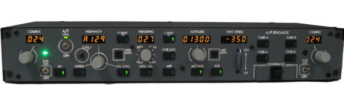
OpenCockpits MCP V3
CRGSim suite
MIP panels
Polabs POKEYS 57E

Polabs POKEYS 57E
BOEING 737 Home cockpit construction history - page 4

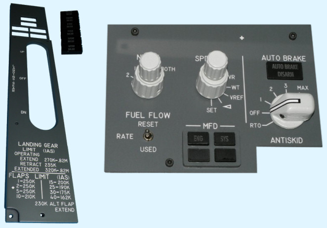
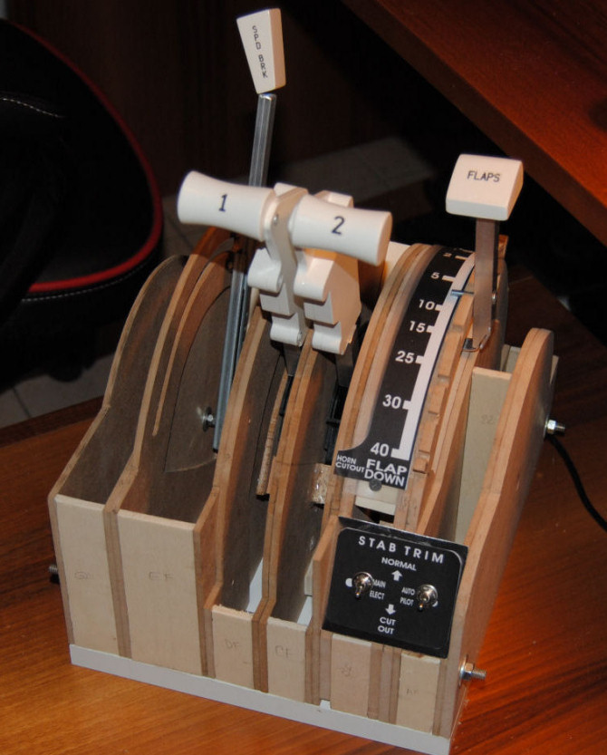
The 737 throttle quadrant.
This is one of the most difficult and complicated step. As you see in the image above the TQ is made by so many parts that you have to design, cut, set together in the right sequence and with the right distances between each other...
If it had been already available when I built mine, I probably would have bought the one produced by Piro Moretta (http://www.flightsimpm.com/), it looks much better and I would have spent more or less the same money I spent anyway at the end, if you consider MDF panels, screws, Saitek throttle quadrant, FlightsimPM levers, and a hundred of work hours... well, for sure it would have been a great deal.
But I must admit that building the quadrant taught me a lot of things, and I am quite proud of my result, even if looking at it now I am sure I could do much better with all the things I have learnt in between.
On internet you can find a lot of tutorials and supporting material like as drawings, measurements, images, videos and so on. I report just a few links, but a simple research will allow to find a great amount of sites that will be interesting to see in order to find out what building procedure seems the best for you.
http://www.scribd.com/doc/55951688/HOw-to-Build-a-Boeing-747-Throttle-Quadrant
http://www.737ngproject.be/throttle.htm
Opencockpits tutorial
http://www.737ngxca.com/throttle.html
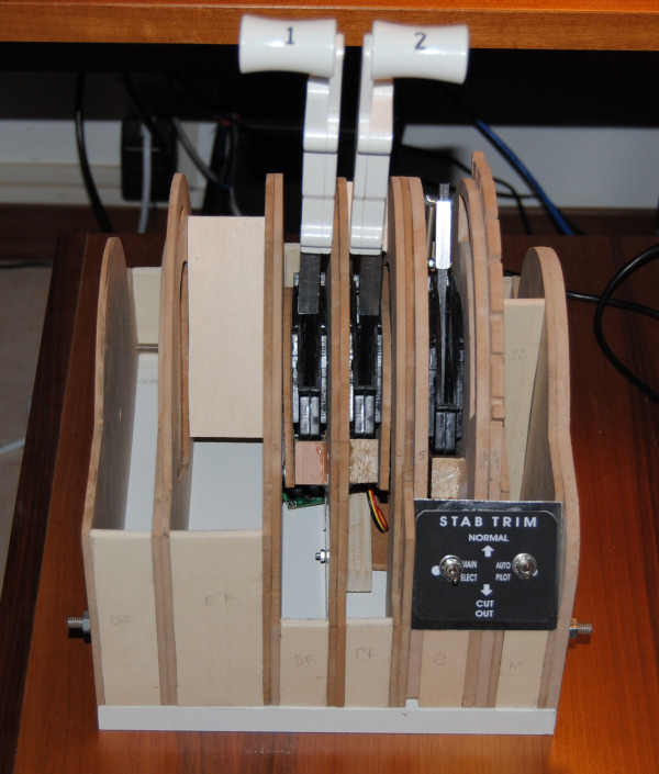
I used the Saitek throttle quadrant for the throttles and flaps mechanics and electronics, following some examples and tutorials I found on the net. This solution offers many advantages : removing the internal shells of the levers from the plastic quadrant, you can position each lever where it must be placed, and it will be completely finished and working as it is : the shell provides the potentiometer (that must be left connected to the Saitek TQ board removed from the plastic TQ) the pivot for the rotation of the lever, the friction necessary to avoid that levers move by themselves under the gravity, and all is already calibrated and ready to plug and play.
A delicate and difficult operation is that of soldering some wires on the small electronic board where are the pins of the micro-switches (pushbuttons), there are at least 6 of them, so you can use these contacts to activate many switches on the new TQ; I used them for spoiler lever (I didn't use a potentiometer for this), for parking brake and, most important, for reverse levers, that I added in a later phase of construction.
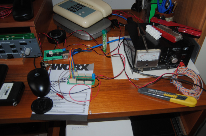
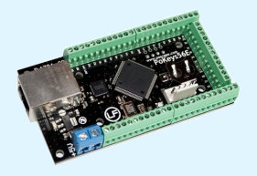
Here I was testing my POKEYS 56E with the led expansion card and a lab power supply set to 5 Volts output. The connection is very simple, you connect one pin of the Pokeys to the switch, then the other side of the switch to the ground and configure that pin as a digital input assigning an fsx function to it via FSSymphony. Then, opening and closing the switch, you see the correspondant action in fsx. As simple as it is, no programming, no problems. The board should even be used to control directly LEDs output, but if you want high luminosity leds it's better to use the expansion board (that you see in the picture) so you don't even need a resistor to protect the led from over-current.
As for the input, you connect one pin of the board to the NEGATIVE of the led, and the POSITIVE to the +5V (be carefull, the negative goes to the board pin!). Then you assign a function to that pin and when fsx changes the status of that particular variable you will see the led turn ON or OFF followinb FSX. Just FANTASTIC!
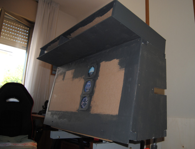
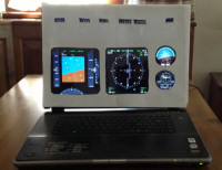
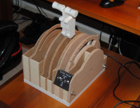
In the meanwhile, I begun painting my MIP with water base paint RAL 7011 that I bought in a bricolage store where the shop assistant prepared the tint for me using the colour composer machine. Using this RAL you are quite sure that engraved panels will fit with the same shade of grey of the base panel.
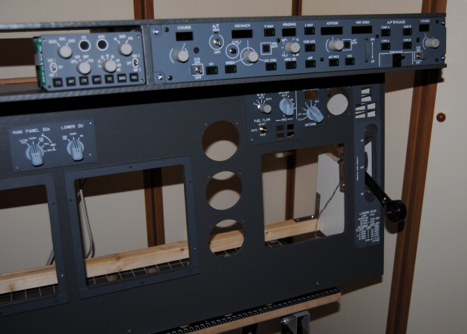
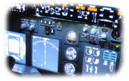
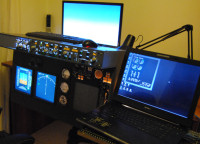
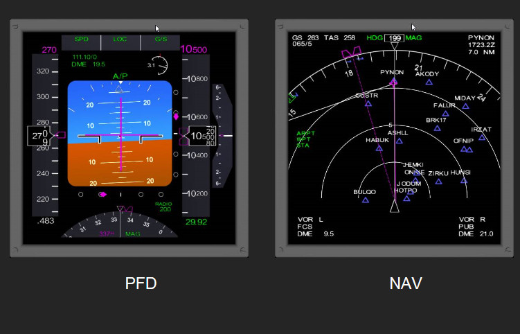
I inserted the MCP and mounted the subpanels. The look is getting better now, and I have also bought an Opencockpits EFIS module. This is more problematic to configure, since EFIS controls differ from plane to plane in fsx, even referring only to 737, not to speak for other airplanes, that have completely different EFIS controls.
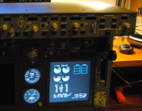
Opencockpits supplies many SIOC configuration text files that can be loaded with SIOC.ini file, but it took me quite a long time to make the EFIS working with default FSX Boeing 737. It works smoothly with PROSIM, but you need to have at least SYSTEM, DISPLAY and MPC modules to get it working. I used the demo version (that is fully functional for 30 mins) to test it, and also in this case Prosim confirms itself a complete and very effective suite for 737 simulation. But since I decided not to use it for its cost, I had to work a lot on my EFIS configuration, till I discovered CRGSIM and the great Kapock Cavanaugh! I will describe the activities carried out by Kapock to make the OC EFIS fully functional with CRGSIM when I will talk about the software tools and configuration.
Continue to THE 737 PROJECT page 5 -->