INVITATION TO BUILD THE DJ9BV'S 144 AND 432 MHZ YAGIS
ABSTRACT:
This relation was presented for first time during the italian eme congress of 2000, and it can consider the practical part of the article of Radio Rivista january 1998 of a DJ9BV's relation presented during the 1997 VHF&UHF congress in Casinalbo di Modena Italy, for the moment i consider only 144 and 432 MHZ yagi, because the 50 and 1296 MHZ need a second article to explain the difference of construction.
This work is devoted to people like me want to make an experience buliding their antenna without spent lot of money and improve their know-how.
Because my study was on mechanic i think to give to you the adequate skill the to make a good work, so i decided to put on this article my experience.
The work i describe is good for anther yagi design when the project use insulated element from the boom.
THE CHARACTERISTICS:
The characteristics of these antennas are :
Maximum gain for a given boom lenght.
50 Ohm impedance allow simple feed structure with folded dipole without any special matching systems.
Pattern with low sidelobes.
Modular project (only first series).
If you put lot of care when you make your antennas you can obtain only a little difference from original project in term of gain etc etc.
PAY ATTENTION : I recommend to read all i put on the biography before start the work.
BEFORE START WORK:
Every time i want to build a yagi i need to draw because it is a full custom project to privilege one thing Vs another for example :
In how many pieces i want to split the boom of my antenna ?
I want to make antennas for single or double polarization ?
I need a double boom or not ? if yes were ?
One yagi for /P use is different from a yagi used for example were there is lot of wind or in a fixed station i need different boom thickness !
In according to the instruction of Rainer you need to add some millimeters to the elements depending of boom diameter !
After you start to answer to theese question, you can draw a divided by ten the natural size of the antenna, so you can know if you need a second boom or the elemente lenght correction.
This process is called: INGENIERIZATION
THE BOOM:
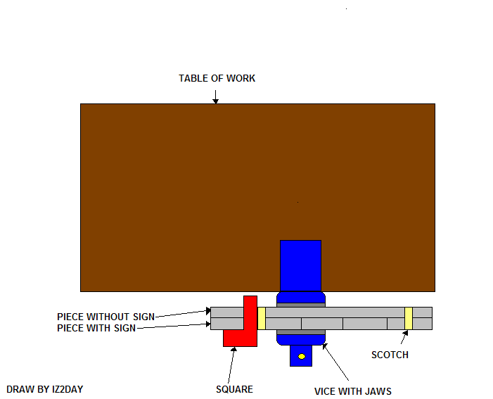
After i choose that anteenna and buy the material i need to square all the extreme side of the parts of the boom, after i need to mark it in this way: forward, center, rear or 1, 2, 3,etc etc.
Put the central part into a vice using a cloth or wood/metal jaws to protect it, after put the other part of the boom into the central part and mark were the other part joint in the central.
Using a long flexible meter and fix it with transparent scotch now you mark with a nail the element position, after measure all position from 0 to x and a second time measure the spacing between all the element to be sure of your work.
With a 90 degrees back square now you mark the position in the middle of the boom and with an hammer and a nail, mark this prevent slide of the tool when you drill it.
If you use a insulator of 8 mm of diameter you need to make the hole in two three times with 4mm,6mm,8mm this prevent the drill looked into the boom and make possible disaster.
If you want to make more than one and do these operations before start to drill: open the vice and put near the marked section another unmarked, fix togheter with scotch now you can square and mark the second piece all time you need !!
Now you can drill all pieces !!
SEE FIGURE to lear the technic i use when i want to build 2 or more yagis
THE ELEMENTS:
The element are simple to prepare were i buy it i found on the market pieces of 105 centimeters long, you need to be careful because the reflectors have not the same lenght like in the first version of 144 Mhz antenna, you need only to find a good store to buy 3 or 6 meter rod.
When i cut the element i see the element show poor elasticity, when was made in Al Mg3 you need to have an extra quantity to make spare element, or to find S11 type rod it is similar to a commercial type antenna elements, if you use S11 i dont know if there are electrical difference beetwen Al Mg3.
Put the element into the vice with the cloth or wood/metal jaws, cut it at right measure with a hand-saw after i square all sides of elements and make a little dribble this help the element wen pass through the insulators, pay attention you don't need to round the sides of element.
A supplier of insulator for 5 millimeters elements is I0JXX if use his insulator you need to cook it in hot water into a pot because they are a little bit small, so you need to enlarge it to permit to the element to pass through the insulator.
THE BALUN:
Like i said before this antenna use the folded dipole to match impedance, we need a special coaxial cable is not the classic RG58 or RG213 but the RG142B/U: it has silvered double shield, teflon dielectric and a silvered single conductor in his center, the dimension are like RG58 but at this cable you can apply more power, sure it cost some time more than RG58 but for this reason i don't consider to use RG58 for the balun.
To prepare and cut the cable in right mode you can follow the instruction and measure of DC6GB article, see the reference.
THE RADIATOR:
Is the most complex part to made but i found it in a flea market also ready to mount on the boom or ready to assembly all single pieces, this second is the best choice for me, but this depend from your skill.
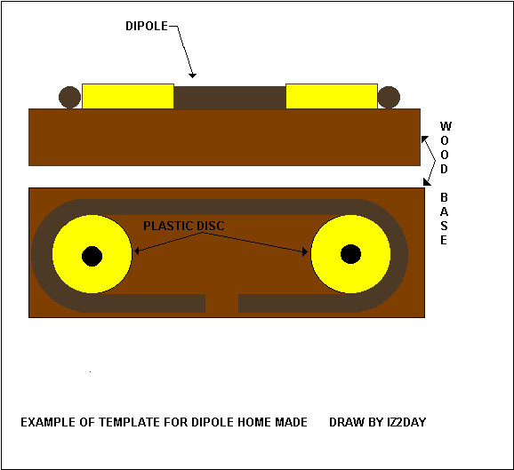
If you want to make dipole by yourself using 8x1mm tube rod you can use this instruction and again the DC6GB article to take the measures , if you make the radiator by yourself follow these instruction: close one side of the rod and make the place for hole of the screw for final assembly, fill inside the rod with sand this help to prevent deformation when you fold it, now fold it all two sides on a pre-shaped template, empty the rod and close the other side.
Another possible way is to have or find a plumber man wich have a tube bend machine, i don't need to find he because i alwais find my dipole in flea market.
Be careful: the spacing distance from the two side of the dipole were there is the screws for final assmbly is 15mm.
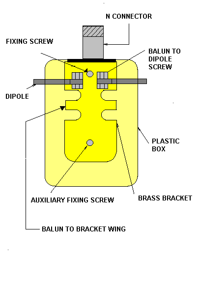
THE DIPOLE BOX:
Is the most important part of this project, if the quality is poor you certainly break your antenna before a contest see the murphy laws.
In my model i mount ABS box from RS it has some some rib you need to remove in this way: using a drilling machine like a milling machine, using the side of drilling tool of 4 mm of diameter at highest speed of the drilling machine fusing the rib.
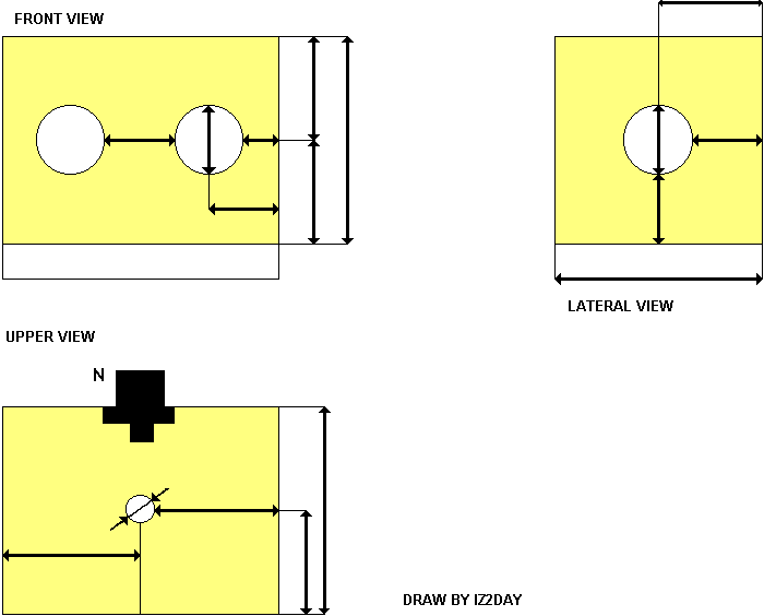
If you use a different box there is no problem, i use RS box because is near my home, i don't encourage the use of electrical distribution box because it hasn't a good shape for this work, so i made a unmeasured template to help you.
But remember if you want a high power antenna (more than 100 watt)forget al type of plastic material use only Tephlon to make this box!
The holes on the box need to make at highest speed also, to draw it on the box you need square and a hoop template because the bow compasses slide a lot on the surface.
The first hole to do is that of the N connector with his mounting screw holes, draw it with connector and brass mounting bracket together, the second hole to make is that of the box to boom screw now you have the position to make dipole feed through holes, and for last you can make the balun feed through holes in a 144 Mhz dipole box, in a 432 Mhz box i use a long box i can bent the balun into the box.
To make a good water insulation use the plastic packing and not silicon because it is corrosive and crumbles easily.
THE BUILDING TOOL:
As you can see the most important tool to make this antenna is the drilling machine, i use one on a table so i can to work in sit down position and i use a small welding machine to make not standard screw.
You need to wear always good proection gloves, glasses and cloth with elastic wristband.
DON'T BE TIRED OR TO MAKE HASTE WHEN MAKE YOUR ANTENNAS: YOU CAN MAKE A MISTAKE ON MEASURE OR HAVE PERSONAL INJURY: SOMETHING IN YOUR EYE, LOOSE YOUR FINGER, ETC ETC.
CONCLUSION:
Now i want to explain something when i start to use this antenna for the first time, is so noiseless because when i connect it to my radio i said:"my radio is dead !" because to listen a signal i need to turn up the af gain.
Homemade is always a good thing for our budget, because if i buy one commercial antenna with same money i can build a four yagi array.
At the end of 2000 i mount to test a piece of one antenna, after one year i see only 2 screw are with oxide because i dont but use inox screws, i don't have any damage by water.
I want to make a special tanks to: I1ANP Mario has gave the plan to me I2FAK Franco, I3DLI Gianpaolo, IK3MAC Graziano, I5WBE Enrico, SM5BSZ Leif, for their improvement in construction, IK5WJD Alessandro and is wife wen i meet they in Florence and last but not least I5TDJ Piero for his time spent with me.
If you belive your work is good for first SEE MY PHOTOGALLERY to see the errors made by me, if you belive your work is good now try to give 1KW to your antenna for on or two minutes and see what the KW do !!!
TO READ BEFORE STARTING :
DUBUS TECHNIK 3:
- Gain and performance data of 144 mhz antennas .
- Gain and performance data of 432 mhz antennas .
- Yagi antennas for 144mhz . (first draw for 2 meter)
- High gain yagi for 432mhz .(first and second drwas for 70 cm)
all wrote by DJ9BV .
DUBUS TECHNIK 4:
- Open feed system for 432 yagi arrays by DJ9BV.
- folded dipole costruction for yagi by DC6GB.
DUBUS TECHNIK 5:
- A G/T study of two meter antennas by VE7BQH.
- Make more 432 eme contact by polarization rotation by G3SEK.
- Switchable polarization for cross yagis by DJ9BV.
- OPT2 yagis by DJ9BV. (second draw for 2 meter)
- OPT70 yagis by DJ9BV. (third draw for 70 cm)
RADIO RIVISTA :
January 1998: il taglia elemrenti wrote by I4CIV .
January 1998: La progettazione di antenne yagi wrote by I4YNO .
Febuary 1993: Effetto boom sulle yagi wrote by I5TDJ.