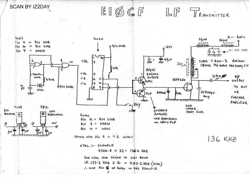
THE EI0CF'S 137 Khz TRANSMITTER
Oh sorry but i not qrv at all here now, but to make a good service to ham community i publish here a letter of EI0CF Finbar O' Connor were he answer to my question, and make correction about his transmitter, i like it for it's simplicity of construction, it is based on a IRFP 450 and it able to use at about 200 Watt range.
It was published on the second edition of: THE LF EXPERIMENTER'S BOOK printed by RADIO SOCIETY OF GREAT BRITAIN the RSGB.
For the owner of this book i want to inform they about the correction is only one: is the value of output capacitor is 470 NanoFarad end not 470 MicroFarad like published in the book.
I publish also a photograph and some detail about EI0CF station were he explain the method to obtain more power about 300-400 Watt at antenna, if you need more power you can use IRFP 460 (i tell ???)
The two I.C. work one like squaring (4011) and one like divider (4040) if you use the HFE from Philips you can supply at 5 volt DC.
The signal source is a cristal oscillator, if you read other book of lf you can see the frquency stability is about 1 Hz, is not critical to obtain because the divider divide the signal and his stability but you need to spent time at calculator.
If you want make an upgrading you can use a signal generator or a D.D.S. in this way you have a general coverage transmitter.
The last things to say are : the band is allocated from 135,7 Khz to 137,8 Khz is wide 2,1 Khz the differece of waveleight at the edge of the band is 33,7 meters , 2210,7 meters at 135,7 khz end 2177 meters at 137.8 Khz .
EI0CF's Tx
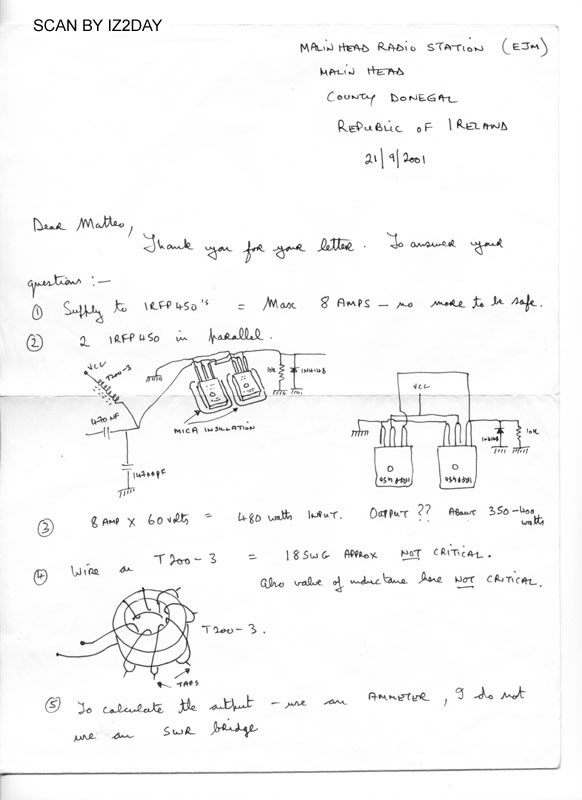
Here is the method of use two IRFP 450 !!!
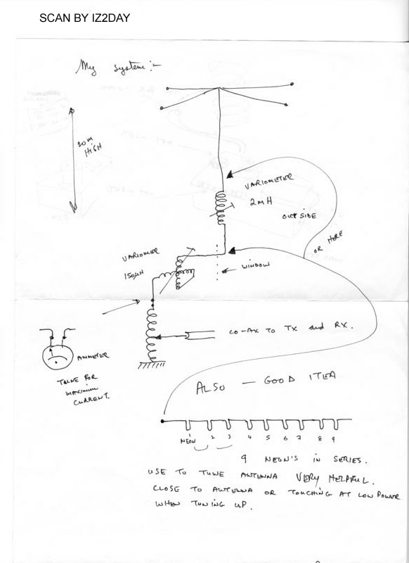
The EI0CF's antenna system .
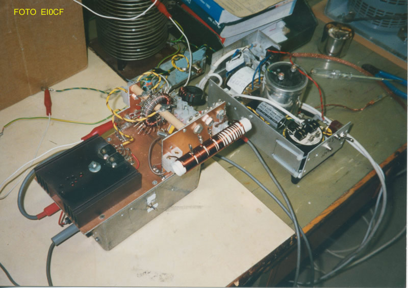
The tx into EI0CF station: the coil in front of the tx is not used, also the coil wounded on black toroid is not used, the box at right is the power supply connected to a variac to make power adjustament of the system, the tx is connected to the antenna by the white wire with the red clamp.