EXPERIMENTS WITH A TUNER "T"
In the summer of 2010 was the third time at the fair in Germany, where i could admire the Palstar tuners not only because they are beautiful, but because they were open, so I could rub our eyes to these beauties !!
In my station, i have 2 tuners, a Magnum MT 1000 D (Italian Brand ) and a homebuilt, come to me after an exchange of material with a friend, the homebuilt tuner does not convince me very on 80 meter, but it work well and sometimes better than the Magnum in other bands, i don't want to sell because it was fitted with a variable inductance and two variable capacitors equal to each other.
In the meantime I started to get the wiring diagram of how configuration will be, before i put my hand into it, so i start to study what my library and internet offer (manual from Palstar and Mfj ) but without much understanding.
Old version maybe LC? the brown cubes are fixed capacitors that allowed the agreement on 160 meters!
Time passes, and one evening at my club station in the spring of 2011, i saw an advertisement in a QST number of the book: "The A.R.R.L. Guide to Antenna Tuners", i immediately thought of buying it, I searched for seas and mountains, but have not been lucky, a last attempt I had left was to buy it in Germany.
Cause financial hardship, I knew one thing: if I wanted to buy the book and the rest of the things i wanted from Germany, i did not have to go there, so I seek someone go in Germany and buy it for me, at the second attempt I found Gilberto IZ2GIL willing to do it.
Two days after the end of the fair, I was holding the book and began to study it within 10 days after the reading flowed smooth as the oil, this book it is easier and simply to understan than the ARRL HANDBOOK and ARRL ANTENNA BOOK in the common parts.
At this point i begins to operate, i desmount the tuner, unsoldered all the wires and connectors, and visit my friend IK2SBB Adamo, in his laboratory he has a capacitance/ Inductance meter, we measured: the condensers was 30/500 PicoFarad and inductance is 25 MicroHenry, said that, I have a new tour to the various diagrams and manuals on the internet.
In 2010, after the German fair I had a pleasant exchange of e-mail with HB9KOF Heinz Bolli, the Swiss representative of Palstar, we discussed some things about antenna tuners for HF in particular two questions I did to him:
DAY: I saw that palstar tuners are "T" and not the classic LC configuration, what are the differences ?
KOF: T-configuration can see at input and output of the tuner a few thousand ohms impedance !.
DAY:I see in most Palstar tuner there is a 1:1 balun input and not the classic 4:1 output, why ?
KOF: the 1:1 balun at the input side of the tuner protect your radiofrom RF on the chassis preserve your final stage also, the 4:1 in output side can break due to high voltages in thatpoint if in has not a good core, and in a T tuners is not necessary !!!

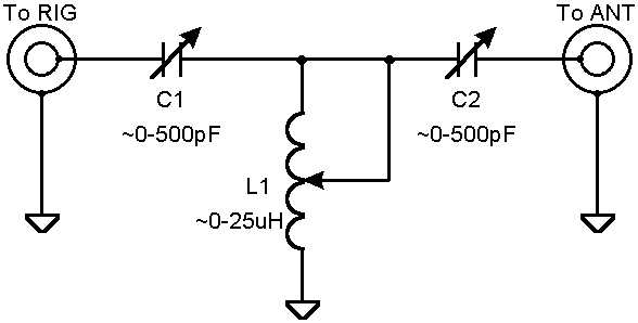
Typical diagram of a tuner to "T", in this scheme there isn't the 1:1 balun at the entrance!
WHAT I HAVE DONE:
Having not yet understood what kind of tuner was before, I put my hands inside, and to listen to the spirit of the investigator in me, I decided to rebuild it in "T"configuration.
I chose to copy the AT4K PALSTAR for clarity of the scheme and the range of output impedances which could also work, and because at the back of the fair in 2010, i had with me a piece of 450 Ohm ladder line waiting to be feed, and this tuner seems to do in my case,this is is one of the reasons for this experiment!.
As in the previous version I used RG 142 cable for connections between switches and SO239.
Again i use the double shiels without internal cnductor and isolator to connect capacitors and inductor.
I used the double shield with external insulator only between T and the output of the antenna switch to prevent discharges.
The center conductor removed from the Teflon insulator was wrapped and sealed on the cables get a job more clean, is also used to connect the switch to the plate to 450 Ohmn(not maked in A release).
For the welding of the RG142 cable, tin and silver was used.
The 1:1 balun comes from an old balun for dipole antennas of Eco(was an Italian antenna brand).
The result is visible in the photo !!
A finished release, the sheet of mylar isolates capacitors and connector by avoiding shock.
OPERATION:
As you can see from the pictures I've made the first experiments using vulgar wires with the heads of crocodiles and I immediately noticed some things that T tuner offers:
The Rx pre tune is difficult to do because you do not notice a change easily the signal to noise ratio!
The W.S.W.R. remains below 1, :1 within 50 kHz of the frequency range where I made the deal!
To give the right inductance i used the table data from the old version of the tuner, but in my case, however, i should study the manual AT4k better than I know now !!!
Always tune with less than 10 watts because when I did the first experiments in 160 with 20 watts dumped me (they were also the first experiments!).
Device Under Test!
IMPROVEMENTS MADE:
For those who intend to build a tuner like this, council to look good photos of Palstar has on its site to see how to wire a tuner in a very good manner, which i didn't this because I want use what i had at home without increasing costs and make too many holes!
In the B release, i follow some of mine friends told me, and i have changed the switch for electrical installations with a ceramic rotary on the out put, i left what i had in the input that switches the input of the tuner or a dummy load outside, I added a plate of tephlon on which I mounted the connectors to feed the 450 ohm balanced line.
But before using the balanced line is necessary to construct a radio frequency current meter because of all the lines must have the same current, otherwise get ready to TVI !!!
Photos of the B version, currently in use in my station, the Tephlon sheet is visible in the lower left of the switch.
The wire that goes from the switch to the ground serves for the future balanced line operations !
OTHER EXPERIMENTS TO DO :
So how is this tuner, is a high pass filter, if you're lucky and replace the two condensers with two inductors and the inductor with a condenser you have a good low pass filter.
In the download page of my site you will find at the bottom of the manual dell'AT4K Palstar and an article of W4ULD about the "T" tuner in general.
My lab after I built the version A of the tuner!
BY AIR :
Version A (July 2011) was fine on all bands except at 24 MHz where for excessive fall of the RF tuner did not want work, arrangements were retouched every 50 to 60 KHz, except that the twenty meters where i find the best match to 14,350 kHz and 14,000 kHz, W.S.W.R. is lees than 1.5, in eighty meters in 3560 where I know my antenna don't need the tuner the W.S.W.R. not pulled down more than 2-2.5 W.S.W.R. !!
Version B (March 2012) is much better at 24 MHz in good agreement with no retouching in band, in eighty meters to go I think I can very well be granted from 3500 to 3650 but I have to retouch every 20 khz! in other bands including twenty meters ok as in version A.
For the measurements was used the SWR meter inside of my ic 735!

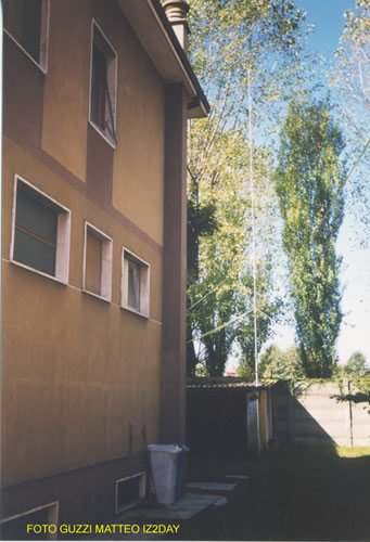
My antenna.