FitPlot is a layout program for images / PDFs. Here you can import almost any kind of graphic file (jpg, tif (also multipage), tga, gif, png, psd, eps and PDF (also multipage)). vers. 3.5: it is possible to insert images or graphical objects (mix of text and graphics) simply copying them from other apps (a graphic program, for example) and pasting them into a FitPot document area.
Its main window (see screenshot) represents your printer / plotter page as set in the page setup (or in the quick page size fields).
You can move, rotate, resize, clip your images as you want, manually or numerically.
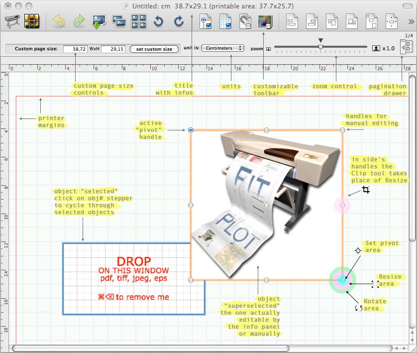
Let's present the program with its main window screenshot:
Screenshot
Usage
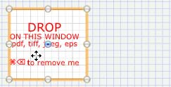
Simply talking, the program is very intuitive. To import an image you can either insert from the file menu or by the insert tool
in the toolbar (we will see the toolbar later), but the simplest way is to use drag&drop: select one or more images file on your disk and drop them on the FitPlot white area. You can also drag and drop images from another program or even from the web (drag from browser).
Note: you can perform some automatic operation while importing images (resize, rotate, apply styles, automatic packing). This can be useful in cases such importing a folder of images for a quick print of previews. See insertion preferences here.
Once on the FitPlot area images can be modified in their size and orientation, can be clipped to make some part disappear, can be placed everywhere, even out of the working area. Can be moved back and forth the image stack and you can apply them some style as trim marks, dashes and strokes, shadow and transparency (only for PDFs), show tag with file name, date, size and path.
Workplace Organization
The main window is so organized:
The window title:
it contains informations about the name of the document and the current page size (bracketed the printable area size, according to the margin settings, see installation -> test your printer).
The toolbar: just below the window title, the toolbar hosts useful FitPlot command, at a mouse click. Fully customizable to your needs. See toolbar paragraph here.
The "environment" settings: below the toolbar you can see
The quick page size control:
(it is quicker compared to the usual page setup menu as usual there in the File menu);
the page setup… button has the same function of the File -> Page Setup… menu and is a quick way to have at hand all sizes proposed by the installed printer drivers. Custom size fields and SET push button allow the setting of any custom page size.
More centered you can see the unit of measure control
you can choose from centimeters, inches and points.
The zoom control (a slider with three buttons, the left one for the min, the right for the max and the center arrow for the 1:1 zoom)
lets you resize your view of the sheet from a minimum of 0.1 (click to the left) to a maximum of 4.0 (click to the right), passing through intermediate values.
A shortcut is available on the keyboard (click with the mouse while holding down space+command keys to obtain a one step zoom+, click with the mouse while holding down space+command+option keys to obtain a one step zoom-). With the same keys combination, but dragging the mouse, you obtain a box-zoom, that means the boxed area will fit the visible area (zoom in).
Furthermore you can live zoom using the mouse scroll ball (or scroll wheel) while holding the alt (option) key.
Toggle pagination drawer: at the extreme right there is a little button, grayed by default, that is used to open the pagination drawer. This button is enabled only if you set the FitPlot document to more than just the single default page. (See pagination for further explanations).
The "sheet" area:
this area, surrounded by the vertical and horizontal rulers, is where you make the layout of the objects to print. Drop here images from your disk or from another application, move, resize clip etc.. This area represents the sheet your printer will paint on.
You can control the editing manually with the mouse or more precisely with the info / edit panel.
Other object manipulations can be done with some commands in the toolbar.
Useful hints
Choose plotter sheet size from the usual File -> Page setup menu. Here you can set your own, too.
Save / reopen arranged sheets for later time printing. Margins and paper sizes are saved along with the file.
Save and open as template. You can collect your documents as models for future use.
To know how to organize the template's folder take a look here.
Drag and drop your files from Finder or other program to the sheet area.
Easily move the objects with a grid snap (tools ->grid menu options).
You can move a selected object also with arrow keys (1 pt x step). This is influenced by the snapping on the grid too. The movement amount is equal to a grid step at each keys stroke. Pressing the shift key increase of x5 the value of the arrow movement.
You can use the tools->move menu (command-M) to move all selected objects. A dialog (see figure below) lets you input the deltaX and deltaY values. Just remember that Y values increase from top to bottom of the screen (as the represented plotter sheet first part to come out is the upper one).
There is also a way to move objects around pages (if more than one page is available in the document).
While moving by dialog you can optionally make a copy of what you are moving. >
Drag copy (alt key pressed while you click and drag an object). Mouse cursor will change this way
. A copy will be created at the point where the mouse is released.
You can drag an object and drop it on a page in the pages drawer (available when the document has more than just one page).
While drag-copying (alt key pressed) a copy of the moved object will be placed on the page where it is dropped, maintaining the same relative position on the new page. A drag-move (alt+cmd keys pressed) will move the object as above, without copying it.
Another way to duplicate an object: edit -> duplicate menu (command-d) or the tool
in the toolbar.
To delete an object: edit -> delete menu (cmd+backspace[←]) or use the delete tool
in the toolbar.
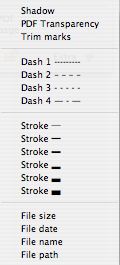
To give an object border, trim lines etc.: tools -> object print styles (or use the info panel, style popup).
Styles can be applied to an image to put trim marks at its corners, set a shadow, frame it with a stroke or dashed line of various thicknesses, add a tag with file name, file date, file size, file path or a custom text.
The caption text can be showed on any side of the image (see info panel extra).
You can apply even transparency to PDF. PDF usually have their white background set to no-print. You can use this characteristic to superimpose a PDF on a background and make other peculiar tricks as in the scenario 4 example.
You can arrange object in the usual Mac way (tools -> bring to front, send to back etc.).
Contextual menus (right click with mouse) on objects to access most of the above operations.
Move around your view clicking the space bar (as in common graphic programs, the cursor become a
).
Double click an any image in the view. This cause the file browser to open in search of an image to replace the double-clicked one.
To avoid watermark FitPlot Demo in printing, obtain your unlocking password. See instructions in the about FitPlot... menu.
Manual editing
To activate manual editing, click on the icon
on the toolbar. Once activated, the icon should change in
(manual editing ON). To toggle it OFF, click it again.
With manual editing OFF you can only use the mouse to move the objects (click and drag), this is more practical, if you want not to resize / rotate, because the object area is all reserved to this and, especially with small images (or low zoom) and manual editing ON, it could be difficult to find space to move an object via click and drag.
Instead, with this option enabled, you can freely resize and rotate images around a chosen "
" pivot.
Selecting an object, 9 handles appears on the image borders (and center). Around the handles there are sensible areas (see screenshot above) where you can see your mouse cursor change according with the operation you can perform on that object. Click and drag to perform operation in real time.
Operations are:
resize
rotate
clip
set pivot
move
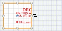
Manual clipping
you can manually clip an image just clicking and dragging the side's handles.
While approaching the image side's handles with the mouse (with manual editing on), your cursor changes in
.
Click and drag toward the center of the image to clip the image. Note that in FitPlot versions previous to 2.2 these handles also was for resizing (
). Now resizing is possible only on vertex's handles.
Furthermore you can reposition the image inside the new clip area clicking and dragging it with the mouse while holding the command key pressed (the cursor changes in
).
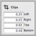
Clipping is possible also numerically through the info panel.
The grid
To help manual editing you can activate / deactivate the grid and the grid snap:
snap to grid off/on
grid visibility off/on
The grid step is configurable in the general preferences.
Clicking and moving an object while the grid snap is on, makes the object to hook to the grid with the corner where the mouse has started dragging.
This is true even with resizing, rotating, clipping.
The magnetic guides
To create a new guide, just click on a ruler area and drag the mouse on the drawing.
Click and drag a guide to move it elsewhere.
Guides fasten on objects leading points (objects must be selected to "attract" guides).
The fasten between guide and point (and vice versa) is evidenced by "snap" sound.
Snap to guides is always on, of course if at least a guide is present.
To place exactly a guide, just double-click it and set the value in the showed field .
To get rid of a guide, just drag it out passing over the ruler parallel to the guide you are moving.
Snap distance and guide color are customizable in the preference panel.
The info / edit panel
As we have seen above, manual editing is one way to operate making up the layout.
The other way, more powerful and precise, is the use of the info / edit panel.
It is visible by default, but, just in case, you can recall it from menu Windows -> Show info (cmd-i).
Also the in the toolbar you should see the push button that shows/hides the info/edit panel.
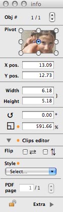
It brings a free rotation field, a free scale% field, numerical positioning fields, width or height constrain fields, clip controls and other goodies and it is a powerful object editor/inspector.
Selections & super selections
When one or more objects are selected, a coloured ring surround them.
The ring colour may be orange or cyan (tough you can change these colors in the general preferences). Cyan means that the object(s) is(are) part of a selection of more objects. Orange means that the object is part of a selection and it is also the "super selected" one. Each selection has always one member that is super selected. This one is the object we are referring to with the info panel.
You can use the stepper to cycle through the selected objects Obj #
1/5
On the main window you should see, between the selected objects (cyan ring by default), one with a different selection ring color (orange by default). This, together with the little thumbnail in the info panel, should let you easily recognize which object the info panel is referring to.
Use of the pivot point "
":
You can numerically establish the position of an object writing numbers in the Xpos and Ypos fields. NOTE: handles refers, in this case, to the current object bounds (that will be different from thumbnail representation when the objects is rotated).
While using rotation and scale fields, instead, the pivot has in the object the same position as in the thumbnail, being the hing for the operation.
The same behavior (handles that follows possible rotation) we have on width and height operations, so if the object is rotated 90°, the width value we type refers, in this particular case, to the "visual" height. This may be deceptive, but so it is.
Vertical and horizontal symmetry operations (flip) are performed always on axis passing by the central pivot.
The clipping drawer: click on the little arrow to open the drawer and edit image clips numerically.
IMPORTANT: numeric fields Xpos, Ypos, width, height, angle, scale, clippings accept input of mathematical operations, automatically calculating the result. For example you can input 3+3*5 and it will turn out to be 18.
The style popup shows / edit the print style for the object.
You can choose one or more items between these:
If the object is a pdf (or even a tiff) with more than one page, you can choose here which page to display / print. PDF page 1/5
You can use the stepper to cycle through the available pages. You can use the keys pageUp, pageDown, Home, End on the keyboard too.
The padlock at left bottom
lock /
unlock objects. This may be useful to prevent unwanted moving.
An extra drawer has been added to shows path, image type, size and bounds of the selected image.
To open it click on the Extra arrow at the lower right of the main info panel.
The Tag side slider (enabled if a text tag style is selected) orient the caption on one of the four sides of the image.
The Custom text field (when custom text style is enabled) lets you type the desired custom text to show on the image side you select with the above tag side slider. The custom text can be concatenated with the other text styles (size, date, name and path).
The Change link push button brings up the file browser letting you choice another image to replace the one the info panel is referring to.
The Reveal push button show you where the image resides on your disk and alert you if the image is not found.
When just imported, an object is at its "natural" shape represented by scale=100%, rotation = 0, all clips = 0. Modifying it (resize, clip or rotation), a little orange • point appears next to the modified fields to show the object has lost its originality. Resetting a value to the original, will cause the point to disappear.
The toolbar
Just below the window title, there is an area designed to host the most frequently used commands. It is visible by default. Just in case it is hidden, you can let it appear from the Windows menu, Show / Hide the toolbar.
Here you can see also the menu to customize the toolbar. In fact you can choose which of the several tools you prefer to have at hand. Just drag the item toward the toolbar to have it available. Drag away from the toolbar to let it disappear from the bar. NOTE: each available toolbar command has always an equivalent menu.
Here a brief list of the currently available tools:
Editing tools
Alignment: you can align or distribute a group of object and, last but not least, you can align objects to the printer margins avoiding printer clipping.
In order of appearance:
Align left (if pushed with the alt-key down, align to the left printer margin).
Align right (if pushed with the alt-key down, align to the right printer margin).
Align top (if pushed with the alt-key down, align to the top printer margin).
Align bottom (if pushed with the alt-key down, align to the bottom printer margin).
Distribute Horizontally (if pushed with the alt-key down, distribute vertically).
Center in Printable Area
packing: pack spaces to optimize paper usage. If pushed with the alt-key pressed the packing will be performed without dialog, according to the current packing preferences. See packing instructions.
rotation:
A selected object can be rotated with the above push buttons. Each click rotates +/- 90 degrees. While holding the alt key, each click gives +/-45 degrees rotation.
To obtain free rotation use the info panel or the editing manual mode.
lock: lock / unlock (while alt key is pressed) selected objects
delete: delete selected objects
Environment settings tools:
manual editing off/on
snap to grid off/on
grid visibility off/on
set images quality (screen) low (editing) / high (printing) This slider, in the environment preferences panel, allows the image's resolution setting when in editing mode, to speed up the redrawing. To see images in high quality to your screen, switch the above toolbar button to "high". When printing, images resolution used is always the best available for each image.
Note that even when high quality is set, while editing (moving or clipping), low quality image is shown.
Expand PDF tool: suitable for multipage PDFs, in just one click, generates all needed FitPlot document pages (in one column) and add each one the relative PDF page.
Specialized tasks
Here's a series of more specialized tasks somebody may find useful, somebody may not.
You can discover FitPlot versatility in the overview section where use of these specialized commands is explained with "real" examples.
Either you can explore each command dialog clicking on the links below.
The program saves its state every time you quit it, so the next time you start it, you will find the same settings you left.
This comprehends units, display settings, page settings, window size, info panel presence.
These same settings are saved with every file you save.
There are some more general preferences that you can save and will be common to all documents and they are showed in the preference panel.
From FitPlot 2.6 the panel has been logically rearranged in tabs, also because more options has arrived in 2.6 and more have to come in future version, so a re-organization has been needed.
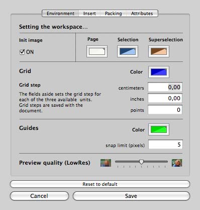
Environment preferences
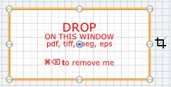
Init image: if checked, the initImage is automatically inserted when a new document is created. It may be handy because just double clicking on it, opens up the dialog to replace it with another image in your disk.
Page, grid, guides and selections colors: use the color picker to set color FitPlot uses to show the page background, the grid color, selection and super selection rings and guides color. The non white background may be useful because in images with white borders (with grid not visible) can be difficult to see the real image bounds on a white background. NOTE: the page color has no effects on printing.
Grid step: configurable for the three units available. You can decide to have a grid of 0.125 " or 2 cm or whatever you want. The grid step is saved as general preference (for new documents) and even with the document data (a saved document retains these settings).
Guides snap limit: this value establish the distance where magnetic guides have effect on objects sides snapping.
Image's quality setting (for editing): This slider, in the environment preferences panel, allows the image's resolution setting when in editing mode, to speed up the redrawing. To see images in high quality to your screen, switch the above toolbar button to "high". When printing, images resolution used is always the best available for each image.
Note that even when high quality is set, while editing (moving or clipping), low quality image is shown.
Pasteboard behavior preferences (outdated since v. 3.5)
This panel has been overcome by the new version 3.5. Now images copied from other programs (or via Drag&Drop from browsers) are always saved (in a temporary directory).
If you decide to save the document with such images, you'll be requested to save them, where you decide, using a prefix (so that the images will be named with your prefix plus a progressive number).
If you choose not to save, quitting the document will free the temporary images folder.
This has been necessary to give all images the possibility to use the new images adjust feature.
A side effect of this new behavior is that pasting images from a vectorial program, will preserve its "vectoriality", saving it as a PDF, with all advantages (resizing with no loss of quality).
Use of symbolic link.
Another problem with linked images was uprising when, after a document was saved, the linked images were moved to another place. Reopening that document, the broken link logo showed up in place of the no more found image. This has been solved with the automatic use of alias, so an image imported in a FitPlot document should be always trackable, even if moved some other place on the same disk.
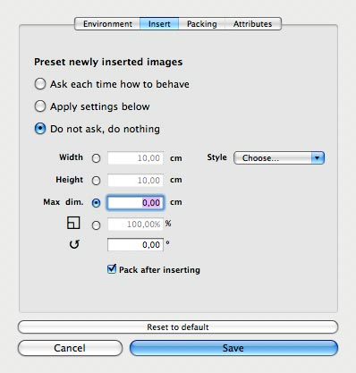
Insert preferences
Here you can establish how to behave when inserting new images on the FitPlot area. These regards resizing, constraining, rotating and applying styles as well as packing after insertion.
As explained before in the PBoard preferences, you may prefer to be asked each time if apply presets or not, and apply or not automatically.
Width, Height, Max dim and Scale% let you resize the newly imported images. To be neutral in resizing, choose scale % and leave 100 as value.
Rotation lets you rotate of the given angle (in degrees) the just imported image. Leave 0° for no rotation at all.
Style: here you can choose one or more from the available styles in the popup list.
Pack after insertion: check this to automatically pack all objects currently in the FitPlot document. The packing is done accordingly to the packing preferences.
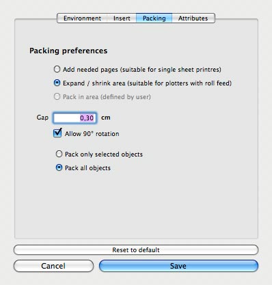
Packing preferences
From the 2.6 version of FitPlot (on user suggestions) the packing algorithm has been improved including now two options, one suitable for users with single page printers and one suitable for plotters where the width is the roll width and the height is virtually unlimited.
Single page: in this case, the algorithm will try to fit images in the page area (if it is possible).
When the area is full, a new page is added and filled with the remaining images, and so on until no image has left.
Plotter with roll: this time the page will be only one, but its size will vary, shrinking or expanding to contain all images. Images are placed fitting the width of the roll and increasing the page length any time is needed (new rows).
Pack in area: images are placed inside an area that the user will be prompted to define.
Gap: this value will be added to separate adjacent images.
Allow 90° rotation: if checked, a calculation will be performed to see if there is a convenience rotating 90° some image (in terms of Y values reached). If convenient the algorithm is performed with possible rotation on some images.
Pack only selected objects: with this option, the packing will be performed only on a selected set of the images on the document. In case of just imported images, these are the "only selected" ones.
Pack all objects: this is the default behavior of the packing algorithm. It acts on all objects in the document, selected or not.
Attributes preferences
Since version 3.5 it is possible to copy attributes from an image and apply the same attributes (paste) to another one. You can copy dimensions (area), angle, shadow attribute, line, dash, tag together with image retouch settings.
Which attributes to copy / paste and which not is determined in the "attributes" tab in the preferences panel. Note: The image adjust panel has its own push button to copy / paste just the image retouch attributes.
About color matching
Many users complain that FitPlot has a bad color management. Their prints that are good in Photoshop, give bad results when printed in FitPlot.
I have not the needed "know how" to give FitPlot all that color management controls as Adobe programs do.
Fortunately, as far as I know from Apple documentation files, FitPlot does manage color profiles by default.
Being a Cocoa Application and making use of the NSView and NSImage classes, automatically each image displayed in FitPlot uses its color profile (if previously assigned). If the image is untagged (has no color profile assigned yet), the program assigns it the default Generic RGB profile (or generic Gray or generic CMYK profiles).
Since version 3.2 / 3.5, FitPlot is able to change the color space of an image assigning it directly from inside FitPlot. Of course FitPlot does not change the original file on the disk, it just creates a copy on the fly. You can find this feature in the new image adjust panel and this is available on raster images only (so PDF, EPS, PS are excluded from this).
Apart this new opportunity, the application itself does not manage directly color profiles, but delegates this task to the underlying ColorSync® technology so it is a good practice to have a previously assigned color profile from other specialized programs or from the image source itself (scanners, camera etc.).
From my daily use, I obtain good results on Epson Stylus D88 and HP Designjet 500PS doing this way:
import an image that has a color profile assigned.
from the print dialog, there should be a Color Matching (or Color Management) option.
Choose ColorSync and print (this forces the ColorSync® engine to match image profile with printer profile doing the needed corrections).
Select the paper / quality (these settings are heavily tied to the printer driver and affects the final result, that is each kind of paper should have its proper color profile; usually manufacturers include presets for the papers they sell).
Is the result good? ("Good" means the printed image matches what you see at screen, except for colors out of gamut).
Of course your screen also have to be calibrated (you can do in ColorSync Utility).
In my experience, using printer manufacturer's papers and inks is the straightforward way to get the best result. I have tried other less expensive photographic papers, experimented some printer settings / adjusting (using the sample images at the next link below) and I have obtained very good results anyway. I have saved these printer custom presets for future use.
For my personal purposes this works very well, but I am not a color management expert. I have made some research on the web and here are some useful excerpts I have found:
"...If our monitor is profiled correctly, and our RGB .tif .jpg is tagged with an embedded profile, FitPlot will display it correctly, and it will print correctly as long as the printer honors the source embedded profile and converts it to a good target printer profile.
Of course except if the file has over-saturated, out-of-gamut colors or tones that the printer inks technology can't reproduce on the chosen paper!..."
"...When you print to a PostScript printer, the Print dialog includes additional options under ColorSync.
The Color Conversion pop-up menu gives you two choices:
Standard. Using this default setting, ColorSync converts the profile data before sending it to the printer. This option is generally faster and more accurate.
In Printer. Using this option, ColorSync converts the source data to a device-independent color space before the print job is sent to the printer.
This device-independent space is then matched to the printer's color space by the printer's PostScript interpreter. This option should be used only when printing to high-end PostScript printers that provide their own built-in color management options.
Printing to a Raster Printer
A raster printer is a non-PostScript printer such as an inkjet printer. There are two ways to print color-managed files to a raster printer:
Use Photoshop to prematch your source data to a printer profile. Choose ‚"Print with Preview" in Photoshop and then choose the printer profile.
Turn off any color correction in the printer driver and print.
If you are printing from an application such as Preview (FitPlot also) that does not provide pre-matching, ColorSync will match your source data to a printer profile. First, you'll need to assign a profile to your printer in ColorSync Utility..."
Disclaimer
Hoping these hints can solve some printer quality issue, I know that there are better application than FitPlot to manage color matching.
Hence, if you need professional color matching, do not base your whole work on FitPlot only, and use, as long as you can, professional color matching tools and programs.
I am not responsible for what FitPlot can or cannot do to your works / products.
I welcome your comments regarding this topic. Please send my an e-mail to .
ColorSync and the ColorSync logo are trademarks of Apple Computer, Inc., registered in the U.S. and other countries.

 >
>