BOEING 737 Yoke column construction - page 1
The 737 yoke column
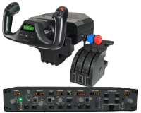
The 737 yoke can be replaced by a Saitek pro-flight yoke (and pedals, otherwise you will miss the steering and rudder control) that is a quite good solution to start with, but it has two major issues :
The first one is that the real 737 yoke is mounted on a column that controls the elevators, while the Saitek yoke has a sliding axle strongly spring-loaded, and this makes the feel of control quite different
from what the 737 yoke should be.
The second issue is that the box that holds the mechanism of the yoke is big and is difficult to arrange it properly in front of the MIP. This problem came out since the very first phase of construction.
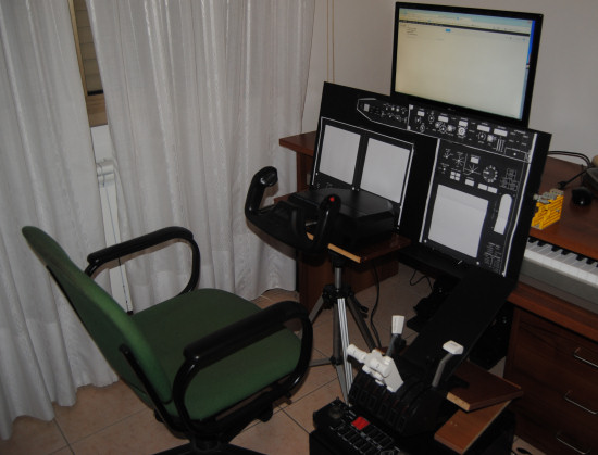
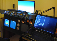
The Saitek yoke positioned in front of the MIP in the very first layout test.
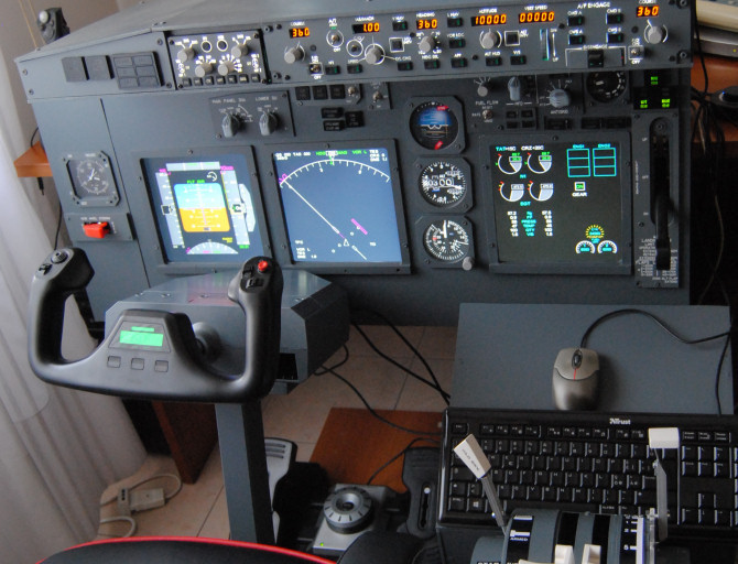
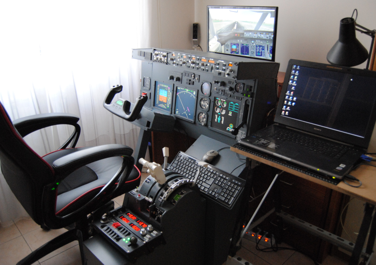
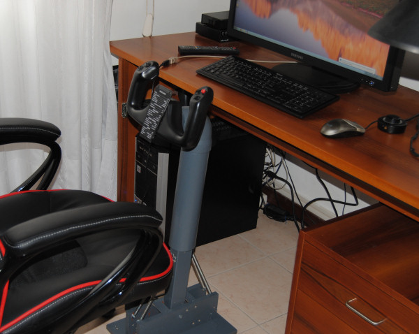
The Saitek yoke in the almost completed MIP, before the transformation in a 737-style self standing column.
I made a wooden stand that holds the box of the yoke at the right height and with an angle that allows a good visibility of the MDF and PDF monitors. But the springs of the axle balancing system make difficult to move the yoke forward and backwards from neutral position, the stand itself moves and it should be screwed to a wider base, but then it would become less easy to remove and store when the cockpit is dismantled. So I eventuallu decided to take the BIG step of dismantling the yoke (or destroying it perhaps) and transforming it in a rotating column like in real B737...
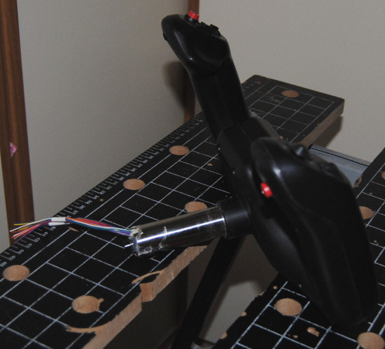
Cutting with a Dremel the axle was not an easy decision for me...
There is no certainty of having your yoke working after this crazy operation!
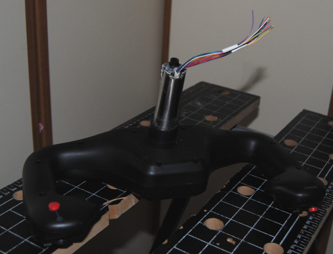
It is essential to cut very carefully (I used a Dremel cutting disk) the steel of the axle all around without getting too deep,
otherwise you will cut also the wires, that must be left longer than the axle in order to connect them again
to the wires coming from the board.
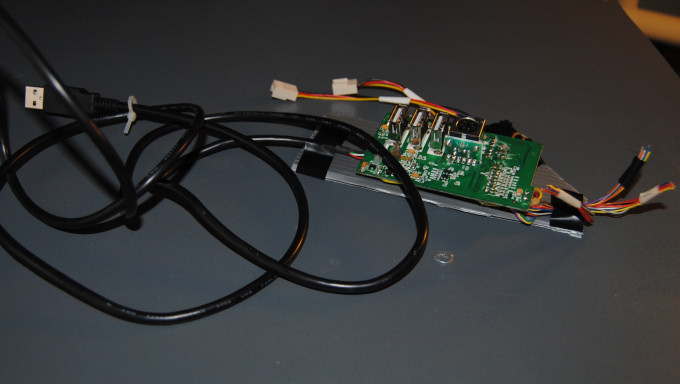
The Saitek yoke USB control board.
The two plugs on the left of the board are the connections for the two potentiometers
for the X and Y axis of the yoke (ailerons and elevator control).
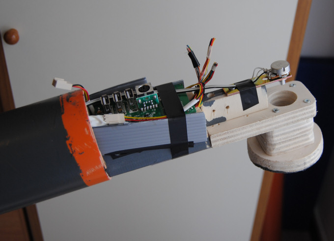
The board installed on the top of the column.
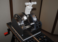
At first I made a set o wood parts screwed together, no bearings, just a 25 mm (1 inch) bore for the axle.
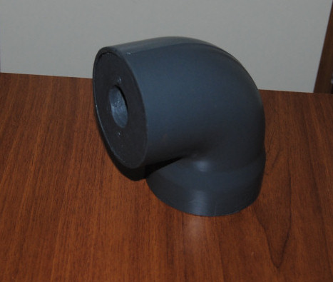
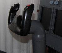
The yoke elbow. I used a 80 mm diameter plastic piping, painted in RAL 7011.
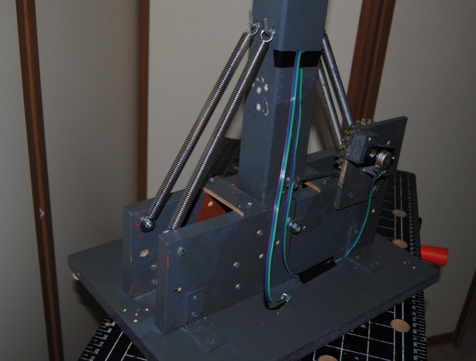
The first idea was to put 4 big springs, 2 on each side of the column. But this solution resulted inefficient, because the load was almost balanced
in the central position, so you had no feel of the neutral position of the control. The springs gave strong forces on both sidede but the resultant force
was almost zero, and so the yoke didn't feel as expected.
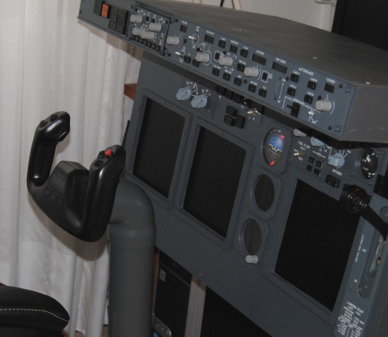
Left spring load apart, this is the result, a very efficient layout also for normal flight simulation, without MIP or other devices.