BOEING 737 overhead panel construction - page 2
Just some days before the end of november 2018 I ordered this overhead panel from
FlightSimPM
I chose this one because it suits perfectly my "closet-cockpit", sizing 60x40cm and so it was almost perfectly adaptable to my supporting frame.
The previous overhead was less wide and shorter, so I had to modify the frame (that slides onto 2 drawers rails) but I managed to make it fit the panel
almost perfectly.
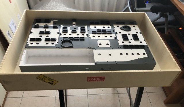
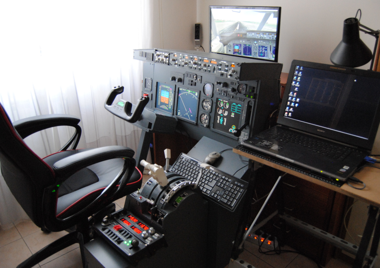
The panel arrived just before the beginning of winter vacations, well packed in a wooden box. This one visible in the photo is the base layer over wich the engraved panels are mounted. The panel includes all the annunciators with their boxes.
The owner of the company, Andi, was very kind and allowed me to send him some custom drawings in order to apply some minor changes to the layout, that were very important to me.

This is the sketch of my custom panel, with the top left corner used for yaw damper, IRS and battery controls. It is not a real
B737 layout, but for me is the best possible solution given my space (and budget) restrictions...!

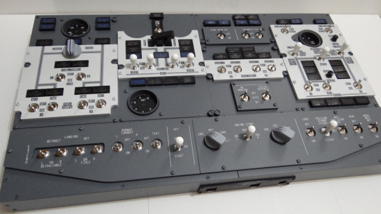
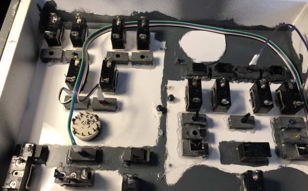
There are so many things to do for completing the whole thing... for the moment I just glue the annunciators. All the switches have been positioned and locked on the base layer. I had to buy 40 new switches on Amazon because the new panel has much more controls than the older one. Unforunately these switches don't have white caps, I will have to buy some dozen of those on Opencockpits.

For a good and uniform backlighting I used some 24V led strips glued on the back panels that closed the overhead box.
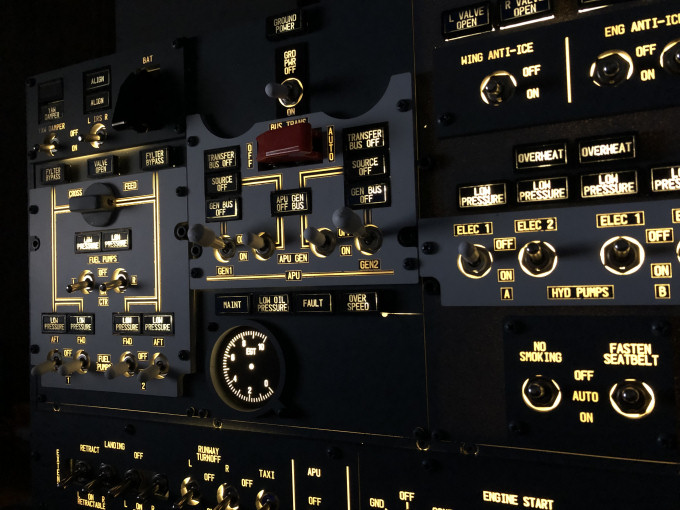
The result looks good. I would prefer a colder white, but probably the thickness of the 2 panels reduces the strenght of the light. Anyway I'm quite satisfied with the backlight. But the most difficult part has yet to come : the wiring and the connection with the control boards. I will still use the Pokeys 57E board with led expansion board since it allows me to re-use the previous code.
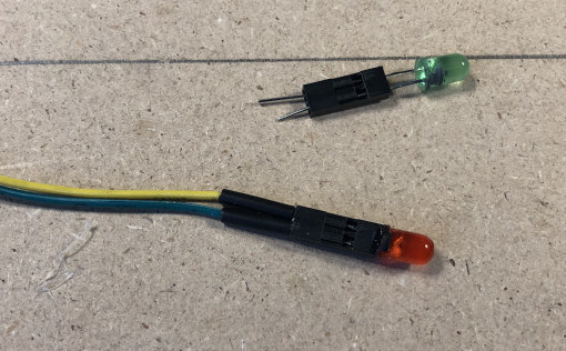
I studied this solution for the leds of the annunciators : a Dupont 2-places plastic cap glued on the base of the led, and wired
on the opposite side with insulating cover on the wires. The head of the led will be inserted in the hole on the annunciators box.
Wiring is a very time consuming process. All wires myst be cut to the proper lenght and crimped on Dupont connectors.
All negative wires and all positive wires are connected to two groups of connectors welded together in order to have just
one negative and one positive wires to the Pokeys board.
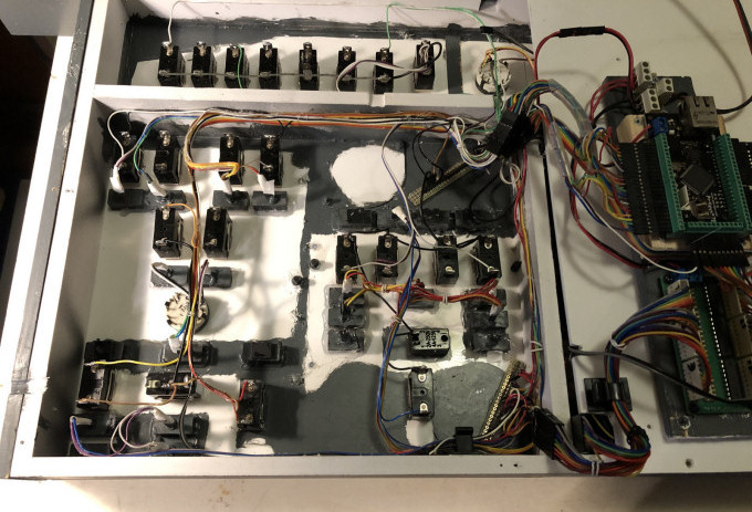
Despite my efforts, the wiring has still some untidiness, but at least it doesn't resemble a haystack.
I decided to thermo-glue the wires along the walls of the frame box, in order to keep them steady, aligned and grouped opportunely.
This will make changhes more difficult, but the thermic glue I use is a low temperature one, so it is not so strong and quite easily removable.
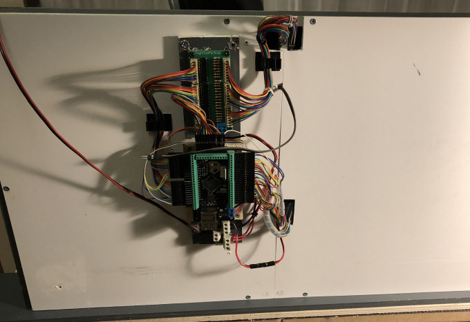
Since the depth of the frame box is only 5cm I had to put the electronic boards outside the box, and I positioned them on the back (that means the top)
letting the wires to pass through some holes that I made on the back panels.
OR
<-- Back to Overhead panel construction - page 1