
After checking twice the connections (just to avoid to smell smoke...) I'm ready to try to write something on the screen.
According with the datasheet, the first step is to initialize the HD44780.
Since I'm using the parallel port (LPT1, set in SPP mode) the output register (8 bit long) is located at the address 0378h (LPT base address, h=hexadecimal notation) : every data I'm writing there will be automatically replicated bit by bit on pins 2 to 9 of the parallel port.
To control pin 1 (connected to the pin RS of the HD44780) and pin 16 (connected to pin E of the HD44780) I have to write on a different register: the control register of the parallel port, located at 037Ah (or LPT base address+2).
This register is used to control some signals of the parallel port and it is linked to pin 1,14,16,17 of the parallel port.
It's 8 bit long but only the 4 high order bit are used, the other 4 (low order bits) are reserved and ignored.
If you want to use the parallel port you must remember that pins 1,14 and 17 are active LOW (pin 16 is active HIGH), that means that if you want to activate one of them you must write a "0" on the correspondant bit of the control register.
The data that the HD44780 can receive are two kinds: commands and characters code to display.
But how our HD44780 can distinguish the kind of data?
Through the value of the pin RS.
If RS=0 (GND) then the data present on Db0 to Db7 is a command, if RS=1 (+5 Volt) then the data is the ASCII code of the character to display.
It's pretty easy, isn't it?
Let's go on.
The first step (MANDATORY) of the initialization is to set the operating mode at 8 bit even if we want to use it at 4 bit.
To do this you must do this sequence: (assuming you are using the LPT1)
write 30h in the output register at 0378h
then
E=1, RS=0 *
delay of 1 millisecond
E=0, RS=0 *
delay of 1 millisecond
(Important: repeat the whole sequence for three times)
* if you used my wiring scheme then to drive E=1 RS=0 you have to write 5 in the control register of the parallel port, E=0 RS=0 write 1, E=1 RS=1 write 4, E=0 RS=1 write 0.
Now the operating mode (8 bit in my case), the number of lines (2), the size of the font to display (5x8) must set.
The sequence is: (only once)
write 38h in the output register at 0378h
then
E=1, RS=0
delay of 1 millisecond
E=0, RS=0
delay of 1 millisecond
Now display ON, cursor OFF:
write 0Ch in the output register at 0378h
then
E=1, RS=0
delay of 1 millisecond
E=0, RS=0
delay of 1 millisecond
Now the last step: the "entry mode set":
write 06h in the output register at 0378h
then
E=1, RS=0
delay of 1 millisecond
E=0, RS=0
delay of 1 millisecond
The initialization is finished.
Now to write a character on the screen we have to select the line where we want the text to appear.
For the line #1:
write 80h in the output register at 0378h
then
E=1, RS=0
delay of 1 millisecond
E=0, RS=0
delay of 1 millisecond
For the line #2:
write C0h in the output register at 0378h
then
E=1, RS=0
delay of 1 millisecond
E=0, RS=0
delay of 1 millisecond
Now to write, for example, a "H" on the screen at the selected line:
write 48h in the output register at 0378h
then
E=1, RS=1
delay of 1 millisecond
E=0, RS=1
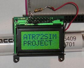
If you are lucky a "H" should appear on the display.
For the other commands (clear display, set cursor at position x,y etc.) I suggest you to read the datasheet.
A technical note:
under Windows 2000/XP you can't access the LPT registers directly then if you want to develop your own software you must use a library that permits the access to the port.
In my case with the Borland Delphi I used the ZLPORTIO library (you can find it easily with Google).
Final consideration:
the LPT port it's easy to manage but it permits to drive only one display (with some trick also 2 displays) but I think that it's pretty limited, it is certainly CPU "power" consuming and we know how important is to have all the CPU power available for FS200x.
That's why I'm currently developing an USB module to drive those kind of displays.
Using a PIC18F4550 (http://www.microchip.com) that supports both USB 1.1 and 2.0 it might be possible to drive up to 20 displays with a single module having a smaller impact on the system than the parallel port.
Of course I will publish a mini-tutorial on how to build it as soon as it will be completed.
<< LCD pag. 2 <<