
____________________________________________
Important note
If you want to try this scheme I hope that you are experienced with electronics and soldering.
Even though I tried it and it is perfectly working, I don't take up any responsibility about damages that might occur to your pc.
__________________________________________________
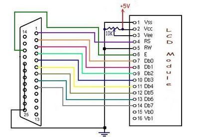
Let's have, then, a closer look to the "thing".
The HD44780 can be set to use two operational modes:
4-bit mode and 8-bit mode.
The scheme above is related to the 8-bit mode, if you want to save some connection and operate it at 4-bit you need to connect the pins Db0 to Db3 to GND (or Vss).
The pin's function is the following:
Vcc : +5 Volt power supply
Vss : GND
Vee : LCD contrast voltage regulator
RS : Register Select (see datasheet for details)
R/W : Read/Write pin (see datasheet for details)
E : Enable pin (see datasheet for details)
Db0 to Db7 : these pins represent the lines through which the HD44780 receives data from the pc
Vb0,Vb1 : backlight illumination power supply
If you don't need to read data from the display, you can also connect the RW pin to GND so that data will have only one direction.
The only things to care of is the time between an instruction and the next (I suggest you to put a delay of 1 millisec. between an instruction and the next, for details see the datasheet).
Vb0 and Vb1 are used to activate the backlight illumination of the display (usually Vb0 is the positive pin and Vb1 the GND but check it before soldering).
Don't connect the backlight directly to Vcc or you risk (in my opinion) to burn the HD44780 out since the backlight lamp is just above the chip and it gets really hot.
Using a 100 ohm resistor (or a bit less) connected between Vcc and Vb0 (assuming that it's the positive pin) the illumination is sufficient and the backlight doesn't get hot (saving the HD44780).
To adjust the contrast you can use a 10 Kohm linear trimmer (or potentiometer) with the cursor pin connected to
Vee.
In the next page I will explain how to drive it through a simple program.
<< LCD pag. 1 << >> LCD pag. 3 >>