


|
|
|
|
In the first figure we can observe the electric scheme of the interface to infrared
from me realized for connecting any cellular, (equipped with the door infrared), to the
PC. I have effected it tries them techniques alone with the Nokia 6150 and 7110, they are
not however there problems of compatibility using other jail cell. 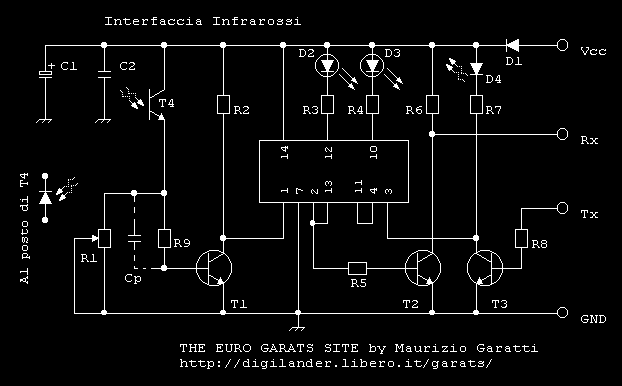 I recommend therefore to read the manual of your mother card attentively in way from not to commit errors. I have inserted however, in phase of planning, two components that absolve to particular assignments. The diodes D1 protect the circuit and your mother card from possible errors of connection. The resistance R6 facilitate the holders of old PC allowing a correct polarization of T2 and therefore a correct transfer given (Rx). Can eliminate this resistance if possess a recent PC! If have problems in receipt insert it! 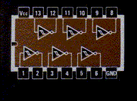 Note: Someone would be able not to be favorable in him to eliminate the resistance R6, in how much the collector of T2 would see correctly not polarized. A resistance of present pull-up on the mother card is exploited really for polarizing the transistor correctly! When your jail cell transmits street infrared, the fototransistor (npn) T4 will receive the signal that will be amplified then by the transistor T1. Thanks to the diode green LED D2 can verify the correct exchange of data. The LED will flash according to the train of wave transmitted. The transistor T2 will transfer the data to your mother card, you see Rx. When your PC will send data to the jail cell, thanks to the infrared LED D4 piloted by the transistor T3, will observe the diode red LED D3 to flash. In case of instability or anomalies, before effecting changes, suggestion to connect the pins to mass 5 and 9 of the integrated IC1 visible in the second photo.
|
