These are some of the electronic circuits I devised and implemented in the past. They are easy to realize and although each circuit comes with some essential information I expect you to be familiar with electronic assemblies and take all necessary safety precautions where applicable. Please contact me if you intend developing any of the circuits as a commercial product.
![]()
Multiple led flasher SCR inverter
Geomagnetic field detector Sound triggered flash
Reverse bias oscillator Noise generator
Seismic detector Electronic I Ching
Electronic attenuator Windscreen loop aerial
Telephone line monitor Zero crossing AC switch oscillator
Power flasher High voltage generator
SCR oscillator Sensitive geomagnetic detector
Zener oscillators Basic infrared TX-RX
220V mains monitor Baluns & coaxial aerials
Ultra low frequency receiver Single led flasher
Electric field detector Long delay timer
Mains frequency meter Electronic relay
Minimal audio oscillators Alkaline charger
5W inverter Car battery tester
LED shine Piezoelectric transformer
Point-contact oscillators 10A car battery charger
Simple warning signal Domestic power limit warning
Light
bulb timer
SCR
audio oscillators
Night light Led light from solar cell
![]()
MULTIPLE LED FLASHER
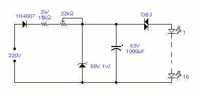 This circuit will flash a string of LED's, typically 16, with
direct connection to the mains and with a period adjustable between 1
and 4 seconds depending on the setting of the 22K/1W pot. Operation at
110V should also be possible but has not been tested. It can be used as
a Christmas Tree decoration, entertainment in general or to flash a
symbol made out of LED's - WARNING - this circuit is implemented at your
own risk! It operates directly out of the mains and proper precautions
must be taken.
This circuit will flash a string of LED's, typically 16, with
direct connection to the mains and with a period adjustable between 1
and 4 seconds depending on the setting of the 22K/1W pot. Operation at
110V should also be possible but has not been tested. It can be used as
a Christmas Tree decoration, entertainment in general or to flash a
symbol made out of LED's - WARNING - this circuit is implemented at your
own risk! It operates directly out of the mains and proper precautions
must be taken.
GEOMAGNETIC FIELD DETECTOR
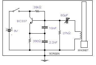 This basic oscillator will detect the Earth magnetic field. The
ferrite rod and coil are taken from an old Medium Wave receiver and a
small magnet is glued at one end. Tune to a medium wave commercial
station until you hear a beat note. Any movement of the ferrite rod will
produce an audible note that depends on the prevailing Earth magnetic
field. Screening is essential. Use a plastic box padded, on the inside,
with copper wires running parallel to the rod and grounded in one place
only. A small hole is made in the box in order to adjust the trimmer
capacitor with a plastic screwdriver. An American equivalent to the
BC337 could be the 2N2369A but I did not try it out.
This basic oscillator will detect the Earth magnetic field. The
ferrite rod and coil are taken from an old Medium Wave receiver and a
small magnet is glued at one end. Tune to a medium wave commercial
station until you hear a beat note. Any movement of the ferrite rod will
produce an audible note that depends on the prevailing Earth magnetic
field. Screening is essential. Use a plastic box padded, on the inside,
with copper wires running parallel to the rod and grounded in one place
only. A small hole is made in the box in order to adjust the trimmer
capacitor with a plastic screwdriver. An American equivalent to the
BC337 could be the 2N2369A but I did not try it out.
REVERSE BIAS OSCILLATOR
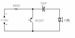 There are a number of npn transistors that will oscillate in the
audio range when reverse biased. Minimum supply voltage is 7V for low
power transistors such as BC109, BC238 and 2N2222A (about 10V for the
latter), it becomes 12V for medium power transistors such as BD139 and
is 16V for power transistors as BUX22 and 2N6543. Current drain is 4mA
at 9V and frequency of oscillation is 550Hz. The base is normally left
open.
There are a number of npn transistors that will oscillate in the
audio range when reverse biased. Minimum supply voltage is 7V for low
power transistors such as BC109, BC238 and 2N2222A (about 10V for the
latter), it becomes 12V for medium power transistors such as BD139 and
is 16V for power transistors as BUX22 and 2N6543. Current drain is 4mA
at 9V and frequency of oscillation is 550Hz. The base is normally left
open.
SEISMIC DETECTOR
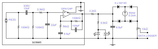 The piezoelectric element of a kitchen gas lighter is used in
this simple, yet effective seismic detector. The piezo element must be
placed vertically, one end solidly to ground. A 2-3 pound weight of fine
gravel in a loose package should be placed on top at the other end. The
high voltage lead goes to the IC, placed close to the piezo element. The
whole box is acoustically and electromagnetically screened. A 3 core
shielded cable brings the signal to the rest of the circuit and to the
power supply (+/- 15V). The SB140 diodes are Schottky type and pin 8
(substrate) of the IC should be connected to ground.
The piezoelectric element of a kitchen gas lighter is used in
this simple, yet effective seismic detector. The piezo element must be
placed vertically, one end solidly to ground. A 2-3 pound weight of fine
gravel in a loose package should be placed on top at the other end. The
high voltage lead goes to the IC, placed close to the piezo element. The
whole box is acoustically and electromagnetically screened. A 3 core
shielded cable brings the signal to the rest of the circuit and to the
power supply (+/- 15V). The SB140 diodes are Schottky type and pin 8
(substrate) of the IC should be connected to ground.
ELECTRONIC ATTENUATOR
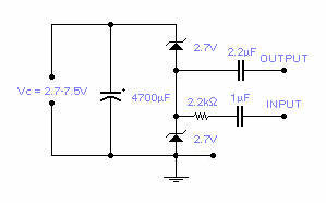 Two low
voltage, low power zeners are used to control electronically the level
of an audio signal. The attenuation range is from 6 to 58dB for an input
current from 0.042 to 77mA corresponding to a control voltage from 2.7
to 7.5V. If control voltage is limited to 5V, the attenuation is around
30dB at a control current of 2mA. This is not an HiFi attenuator but
might come useful as a general purpose audio attenuator.
Two low
voltage, low power zeners are used to control electronically the level
of an audio signal. The attenuation range is from 6 to 58dB for an input
current from 0.042 to 77mA corresponding to a control voltage from 2.7
to 7.5V. If control voltage is limited to 5V, the attenuation is around
30dB at a control current of 2mA. This is not an HiFi attenuator but
might come useful as a general purpose audio attenuator.
TELEPHONE LINE MONITOR
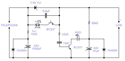 If you feel that somebody is tampering with your telephone line
you might find this little circuit useful. It detects if there is
another telephone connected to the line, if there is a short or an open
line. Sound and a flashing light will tell you which is the current
situation. The speaker is practically cut out during a normal
conversation thus preserving privacy, only the LED will flash
occasionally. The circuit does not require any battery and takes the
supply from the telephone line itself. The transistors used are wired in
a reversed biased fashion thus behaving as oscillators. You might try
the 2N2222A as an alternative (not tested, you may need to increase the
zener to 10V for the 2N2222A). This monitor is, of course, suitable only
for analogue lines. Watch the polarity of the input line: the circuit
will not be damaged by a polarity reversal but it will not operate
correctly.
If you feel that somebody is tampering with your telephone line
you might find this little circuit useful. It detects if there is
another telephone connected to the line, if there is a short or an open
line. Sound and a flashing light will tell you which is the current
situation. The speaker is practically cut out during a normal
conversation thus preserving privacy, only the LED will flash
occasionally. The circuit does not require any battery and takes the
supply from the telephone line itself. The transistors used are wired in
a reversed biased fashion thus behaving as oscillators. You might try
the 2N2222A as an alternative (not tested, you may need to increase the
zener to 10V for the 2N2222A). This monitor is, of course, suitable only
for analogue lines. Watch the polarity of the input line: the circuit
will not be damaged by a polarity reversal but it will not operate
correctly.
![]() I wish
to see more of it
I wish
to see more of it
![]() I
rather go back to the surface
I
rather go back to the surface
![]()
Contact: remove
s from address
remove
s from address