THE ELECTRIC WAVE![]()
 This circuit was specifically designed to recharge alkaline
cells. The unusual connection of the transistor in each charging unit
will cause it to oscillate, on and off, thus transferring the charge
accumulated in the capacitor to the cell. The orange LED will blink
for around 5 times a second for a 1.37V cell. For a totally discharged
cell the blinking is faster but it will decrease until it will come to
a stop when the cell is charged. You may leave the cell in the charger
as it will trickle charge and keep it at around 1.6V. To set the
correct voltage you have to connect a fresh, unused cell and adjust
the trimmer until oscillations set in, then go back a little until no
oscillation is present and the circuit is ready to operate. You should
use only the specified transistors, LED colors, zener voltage and
power rating because they will set the final voltage across the cell.
A simple 9V charging circuit was also included: it will charge up to
around 9.3V and then keep it on a trickle charge: the green LED will
be off while charging and will be fully on when the battery is close
to its final voltage.
This circuit was specifically designed to recharge alkaline
cells. The unusual connection of the transistor in each charging unit
will cause it to oscillate, on and off, thus transferring the charge
accumulated in the capacitor to the cell. The orange LED will blink
for around 5 times a second for a 1.37V cell. For a totally discharged
cell the blinking is faster but it will decrease until it will come to
a stop when the cell is charged. You may leave the cell in the charger
as it will trickle charge and keep it at around 1.6V. To set the
correct voltage you have to connect a fresh, unused cell and adjust
the trimmer until oscillations set in, then go back a little until no
oscillation is present and the circuit is ready to operate. You should
use only the specified transistors, LED colors, zener voltage and
power rating because they will set the final voltage across the cell.
A simple 9V charging circuit was also included: it will charge up to
around 9.3V and then keep it on a trickle charge: the green LED will
be off while charging and will be fully on when the battery is close
to its final voltage.
A
2.5VA transformer will easily charge up to 4 cells at the same time
although 2 only are shown in the schematic. In order to minimize
interference from one circuit to the other they have nothing in common
except the transformer and, in order to show a balanced load to the
transformer, half of the charging units will use the positive sinewave
and the other half the negative sinewave.
All
types of alkaline cells can be recharged: it will take 1 day for a
discharged AA cell or 9V battery and up to several days for a large D
type cell. The best practice is not to discharge completely the cell
or battery but rather to give a short charge every so often although
admittedly this is not easy to achieve.
I tried successfully to recharge NiMH cells as well. Although the charging profile for these cells is quite different from alkaline cells, the circuit seems to work fine provided you do not leave them in the charger forever, because of the possibility of overcharging especially for the smaller batteries.
The mains transformer must be suited for the voltage available in each country: usually 230Vac or 115Vac.
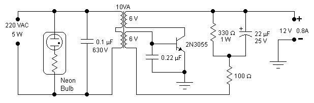 A single transistor is all you need for this simple inverter.
The main aim of this circuit is to provide a suitable supply for all
kind of low power battery chargers that normally connect to the mains
such as mobile phones, electric shavers, etc, even an electronic neon
light rated at 5W was successfully connected. Only easily obtainable
components are used. The transformer is a standard 10VA mains
transformer with two 6V windings connected as shown in the schematic.
Frequency of operation is between 70 and 190Hz depending on the nature
of the load. This frequency is acceptable by most devices but
obviously it is not suitable to drive frequency dependent appliances
such as clocks or small motors that depend on the mains frequency in
order to operate reliably. The transistor will not require any
additional heatsink if it is assembled on the metallic case provided
for the inverter. The neon glow light will give a useful indication,
and warning, on the presence of a dangerous voltage at the output. A
2.5A fuse on the input supply line would be a useful addition.
Operation is simple: switch on the unit and connect the load keeping
an eye on the neon glow light which should be always on: certain
switching chargers demand an initial peak current effectively shorting
the output and switching off the neon: in this case you have to try
repeatedly to connect the load until it works. A temporary short at
the output and a temporary voltage reversal at the input will not
damage the unit. Efficiency was not a design parameter however it was
measured to be between 50 and 60%. If you have a 110V mains
transformer and consequently a 110VAC output you should change the 0.1μF capacitor to 0.22μF,
400V. The waveform is only vaguely sinusoidal. Invert the connection
of one of the 6V windings if oscillations do not set in.
A single transistor is all you need for this simple inverter.
The main aim of this circuit is to provide a suitable supply for all
kind of low power battery chargers that normally connect to the mains
such as mobile phones, electric shavers, etc, even an electronic neon
light rated at 5W was successfully connected. Only easily obtainable
components are used. The transformer is a standard 10VA mains
transformer with two 6V windings connected as shown in the schematic.
Frequency of operation is between 70 and 190Hz depending on the nature
of the load. This frequency is acceptable by most devices but
obviously it is not suitable to drive frequency dependent appliances
such as clocks or small motors that depend on the mains frequency in
order to operate reliably. The transistor will not require any
additional heatsink if it is assembled on the metallic case provided
for the inverter. The neon glow light will give a useful indication,
and warning, on the presence of a dangerous voltage at the output. A
2.5A fuse on the input supply line would be a useful addition.
Operation is simple: switch on the unit and connect the load keeping
an eye on the neon glow light which should be always on: certain
switching chargers demand an initial peak current effectively shorting
the output and switching off the neon: in this case you have to try
repeatedly to connect the load until it works. A temporary short at
the output and a temporary voltage reversal at the input will not
damage the unit. Efficiency was not a design parameter however it was
measured to be between 50 and 60%. If you have a 110V mains
transformer and consequently a 110VAC output you should change the 0.1μF capacitor to 0.22μF,
400V. The waveform is only vaguely sinusoidal. Invert the connection
of one of the 6V windings if oscillations do not set in.
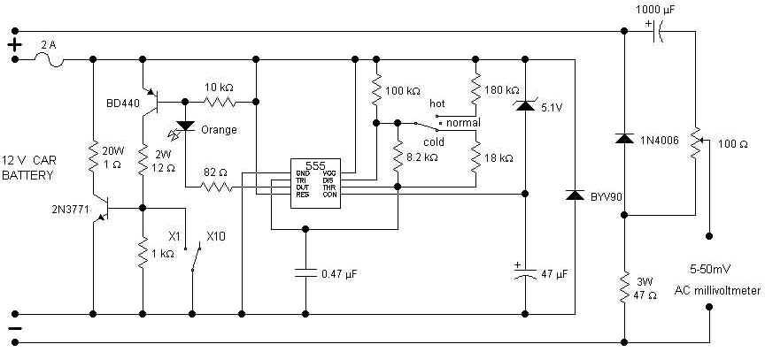 Checking
the status of your car battery (accumulator) should be easier with
this circuit which measures the internal resistance of the battery.
Pulses generated by the 555 are used to drive a dummy load and the AC
voltage which develops across the battery gives an indication of its
internal resistance: the lower the voltage the healthier the battery.
The AC voltage is read out by means of a digital meter connected at
the output. Separate leads are used for the dummy load and for the
metering circuit. They should be connected to their respective battery
lugs but they should not touch each other. This avoids erroneous
readings due to less than perfect contacts of the dummy load. The
internal resistance depends on the battery temperature as well; this
is the reason for the switch: hot means a battery (not
ambient) temperature between 35 and 52 degrees Centigrade, normal
is for a temperature between 16 and 34 degrees and cold is
good for a temperature from -4 to 15. Beyond these ranges the reading
is unreliable. The internal resistance depends also on the rated
capacity of the battery. The 100 ohm potentiometer sets the battery
capacity: it is rotated totally to positive for a 100Ah battery and
totally to negative for a 32Ah battery. A dial with uniform markings
from 32 to 100 was used in the prototype. This means we
can measure internal resistance of batteries rated from 32 to 100Ah.
As there are a number of smaller 12V batteries around, specially for
alarm systems, a switch was introduced that, in the X1 position,
will change the capacity range to 3.2 - 10Ah. The unit has six leads
going out of the box: two for the dummy load, two for the metering
section and two going to the digital meter. Operation is simple: set
the range, temperature and battery rating, then connect the dummy
load and the metering leads to the battery lugs and read the ac
voltage: you should be safe if it reads below 10-12mV otherwise it
is better to give the battery a good recharge and if it is still
beyond 10-12mV then probably you need a new battery.
A bright orange LED shows that the unit is connected and in
operation.
Checking
the status of your car battery (accumulator) should be easier with
this circuit which measures the internal resistance of the battery.
Pulses generated by the 555 are used to drive a dummy load and the AC
voltage which develops across the battery gives an indication of its
internal resistance: the lower the voltage the healthier the battery.
The AC voltage is read out by means of a digital meter connected at
the output. Separate leads are used for the dummy load and for the
metering circuit. They should be connected to their respective battery
lugs but they should not touch each other. This avoids erroneous
readings due to less than perfect contacts of the dummy load. The
internal resistance depends on the battery temperature as well; this
is the reason for the switch: hot means a battery (not
ambient) temperature between 35 and 52 degrees Centigrade, normal
is for a temperature between 16 and 34 degrees and cold is
good for a temperature from -4 to 15. Beyond these ranges the reading
is unreliable. The internal resistance depends also on the rated
capacity of the battery. The 100 ohm potentiometer sets the battery
capacity: it is rotated totally to positive for a 100Ah battery and
totally to negative for a 32Ah battery. A dial with uniform markings
from 32 to 100 was used in the prototype. This means we
can measure internal resistance of batteries rated from 32 to 100Ah.
As there are a number of smaller 12V batteries around, specially for
alarm systems, a switch was introduced that, in the X1 position,
will change the capacity range to 3.2 - 10Ah. The unit has six leads
going out of the box: two for the dummy load, two for the metering
section and two going to the digital meter. Operation is simple: set
the range, temperature and battery rating, then connect the dummy
load and the metering leads to the battery lugs and read the ac
voltage: you should be safe if it reads below 10-12mV otherwise it
is better to give the battery a good recharge and if it is still
beyond 10-12mV then probably you need a new battery.
A bright orange LED shows that the unit is connected and in
operation.
 Full short-circuit
and overcurrent protection is given by this circuit suitable for
workbench applications in technical schools and laboratories where
there is a need to work directly with the mains. Additional features
are a clearly visible red lamp indicating that the voltage is
present, good isolation of the output circuit when the unit is off,
only a few millivolts were measured with no load, current threshold
adjustable over a limited range and the possibility of remote
cutout: the 6V from the secondary can be taken anywhere, normally
where you are working, even far away from the protection circuit.
Pressing the push button will short-circuit the winding and the
circuit will switch off thus removing the mains voltage. A suitable
led is placed together with the push button to show whether the
circuit is in operation or not. Additional remote cutout circuits
can be wired in parallel if so required. The circuit will switch off
if a short is applied at the output without blowing the fuse but it
will blow if you try to activate the circuit if a short is already
present.
Full short-circuit
and overcurrent protection is given by this circuit suitable for
workbench applications in technical schools and laboratories where
there is a need to work directly with the mains. Additional features
are a clearly visible red lamp indicating that the voltage is
present, good isolation of the output circuit when the unit is off,
only a few millivolts were measured with no load, current threshold
adjustable over a limited range and the possibility of remote
cutout: the 6V from the secondary can be taken anywhere, normally
where you are working, even far away from the protection circuit.
Pressing the push button will short-circuit the winding and the
circuit will switch off thus removing the mains voltage. A suitable
led is placed together with the push button to show whether the
circuit is in operation or not. Additional remote cutout circuits
can be wired in parallel if so required. The circuit will switch off
if a short is applied at the output without blowing the fuse but it
will blow if you try to activate the circuit if a short is already
present.
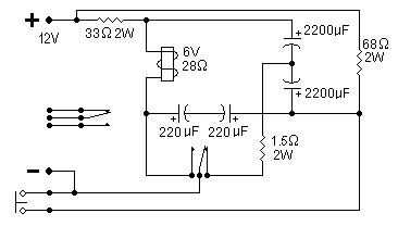 This
circuit will convert a standard relay to a pulse relay; pressing the
button will switch it on and pressing it again will switch it off. For
this purpose you need a relay with 2 sets of contacts: one is used for
the circuit and the other is available for an outside circuit.
Sometimes it is difficult or impossible to find a stepping relay,
normally used in electrical wiring, and this is a viable solution. The
relay used in this circuit was a power relay with 10A contacts and a
coil resistance of 28Ω. The
circuit will draw no power when idle and it is possible to scale up
the circuit to operate at a higher voltage. The relay must be always
rated at half the supply voltage, in our case it is a 6V relay for a
12V supply. The resistor in series with the coil must have a similar
resistance as the coil or slightly higher and the other resistor
should be twice the coil resistance. All capacitors are 25V. The
capacitors value depends on the coil resistance: the higher the
resistance the lower the value. As it takes a certain time to charge
the capacitors it is necessary to wait about 0.5-1sec between one
operation of the push button and the next. An unregulated 12V power
supply is adequate for this circuit.
This
circuit will convert a standard relay to a pulse relay; pressing the
button will switch it on and pressing it again will switch it off. For
this purpose you need a relay with 2 sets of contacts: one is used for
the circuit and the other is available for an outside circuit.
Sometimes it is difficult or impossible to find a stepping relay,
normally used in electrical wiring, and this is a viable solution. The
relay used in this circuit was a power relay with 10A contacts and a
coil resistance of 28Ω. The
circuit will draw no power when idle and it is possible to scale up
the circuit to operate at a higher voltage. The relay must be always
rated at half the supply voltage, in our case it is a 6V relay for a
12V supply. The resistor in series with the coil must have a similar
resistance as the coil or slightly higher and the other resistor
should be twice the coil resistance. All capacitors are 25V. The
capacitors value depends on the coil resistance: the higher the
resistance the lower the value. As it takes a certain time to charge
the capacitors it is necessary to wait about 0.5-1sec between one
operation of the push button and the next. An unregulated 12V power
supply is adequate for this circuit.


 If you
wish to have some really nice looking LED's shining out of your
equipment panel, you may try the following trick: pass repeatedly a
fine sandpaper on the surface of any transparent and clear LED until
the same surface is all worked out to a whitish look.
If you
wish to have some really nice looking LED's shining out of your
equipment panel, you may try the following trick: pass repeatedly a
fine sandpaper on the surface of any transparent and clear LED until
the same surface is all worked out to a whitish look.


 There
is
nothing else to do but to switch it on and enjoy the pleasant look of
it. Do not use the extra fine sandpaper as it will not cut deep enough
in the LED plastic material, in other words the sandpaper normally
used for metals is not suitable. As the difference with a standard LED
was remarkable I did some tests in order to compare
There
is
nothing else to do but to switch it on and enjoy the pleasant look of
it. Do not use the extra fine sandpaper as it will not cut deep enough
in the LED plastic material, in other words the sandpaper normally
used for metals is not suitable. As the difference with a standard LED
was remarkable I did some tests in order to compare
 them: picture 2
and 5 refer to the normal clear LED, red in these tests, shining right
in front of a screen and tilted at about 60° respectively. The results
were as expected: very bright when viewed on axis and dimmer when off
axis. The same LED (picture 1 and 4) after the "treatment": it is
slightly dimmer when viewed right in front but it is much brighter
when it is off axis and it gives a much better overall appearance.
Picture 3 and 6 refer to a standard diffused LED and as one can
clearly see, it is just too dim. The white part of the picture is
where the light is most intense and full of infrared light. As most
digital cameras are quite sensitive to infrared light, it is recorded
as a white area. This is not really a circuit but I thought to share
it with you and unless you need the extra brightness of a front
shining LED you may use this trick with any clear LED, blue LED's
being especially attractive.
them: picture 2
and 5 refer to the normal clear LED, red in these tests, shining right
in front of a screen and tilted at about 60° respectively. The results
were as expected: very bright when viewed on axis and dimmer when off
axis. The same LED (picture 1 and 4) after the "treatment": it is
slightly dimmer when viewed right in front but it is much brighter
when it is off axis and it gives a much better overall appearance.
Picture 3 and 6 refer to a standard diffused LED and as one can
clearly see, it is just too dim. The white part of the picture is
where the light is most intense and full of infrared light. As most
digital cameras are quite sensitive to infrared light, it is recorded
as a white area. This is not really a circuit but I thought to share
it with you and unless you need the extra brightness of a front
shining LED you may use this trick with any clear LED, blue LED's
being especially attractive.
![]() Eager for more
Eager for more
 Full astern to main page
![]()
 remove s from address