![]()
![]()
![]()
![]()
![]()
![]()
![]()

![]()
If high temperature is a problem we can try to lower using a cheap device: the
Peltier cell.
Most cooler for Personal Computer microprocessor are expensive and unsuitable
for Terrarium.
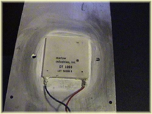
In December 2000 during the annual Radio Ham Bazaar I bought some Peltier Cells for 10$ each.
The supplier is MARLOW INDUSTRIES INC.
Follow the technical data:
Physical dimensions
:
40 x 40 x 4 mm
Max operating current : 5.5 A
Max Voltage
: 16.7 V
Maximum dissipated Power : 55 W
Delta T max
: 60 degrees Celsius
Part
Number
: DT1069 (maybe discontinued)
Anyway I think any 40x40 mm with similar above specs might work fine.
*** IMPORTANT NOTICE ***
Circuit should be tested by people who has sufficient knowledge in electrical mountings and mechanical assembly. This circuit is intended for educational use only. Authors of the design are not responsible for any damage caused by this project. You will test this circuit at your own risk.
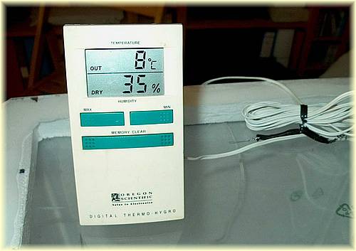
HOW IT WORKS
The tank allows a temperature difference of 13/15°C between inside and outside
with a power consumption less of 25/30W.
For example: if room temperature is 25°C, you may low temperature down to 12/10°C.
It means that if you want to low temperature to 5°C room temperature must not exceed:
5 + 15 = 20°C
On the other hand if room temperature is 35°C this circuit will
drop temperature down to 22/20°C.
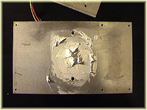
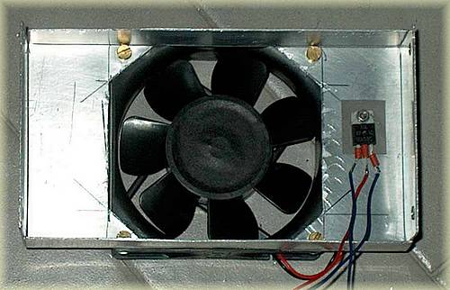
Take special care to the heat-sink dimension and to the forced air system, the Peltier cell will work only if hot side temperature is close to the ambient temp. Due to poor thickness of the cell, an aluminum parallelepiped will be necessary to lengthen cold side. Use thermal grease to increase efficiency on both sides.
A 3 mm thick aluminum sheet will complete the cool side.
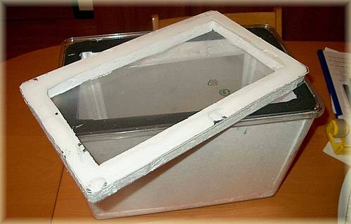
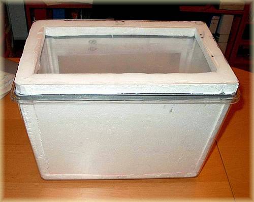
The insulated container is basically a fridge, so if you like it
is possible using a commercial one. The only difference is the cover that
must be clear and transparent. I used two plastic sheets sticked with polystyrene
frame. Also thin glass sheets should work well but are fragile.
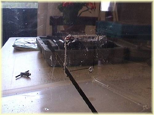
THE TANK
The starting point is to open a window in a commercial plastic fish tank.
If you decided to build tank by yourself, maybe you need a "special tool" for cutting polystyrene sheets. In this case you might build it modifying a solder iron as shown :
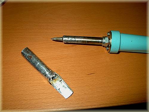
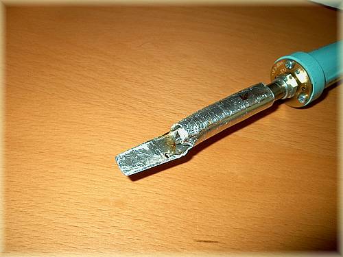
It is made with aluminum sheet 1mm thick
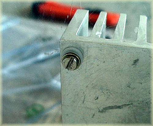
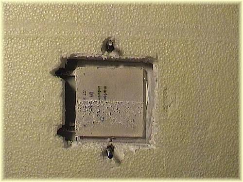
Then fix the heat-sink to the tank keeping a distance of 2-3 from the tank by the use of plastic washers.
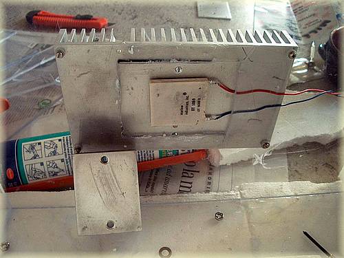
Place a sheet of polystyrene and the aluminum block on the cold side of Peltier cell after having spread thermal grease on both sides.
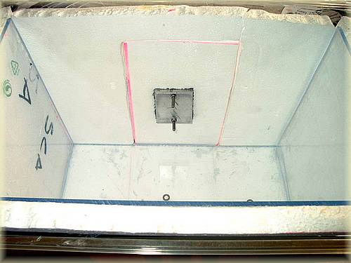
Place polystyrene sheets and interior plastic sheets, temperature sensor, and cooling plate. To increase thermal efficiency stick a plastic frame (black sponge) as shown.
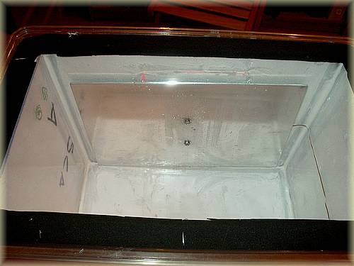

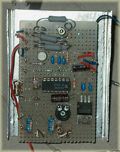
Tank construction is finished. Now build the electronic circuit.
THE CIRCUIT
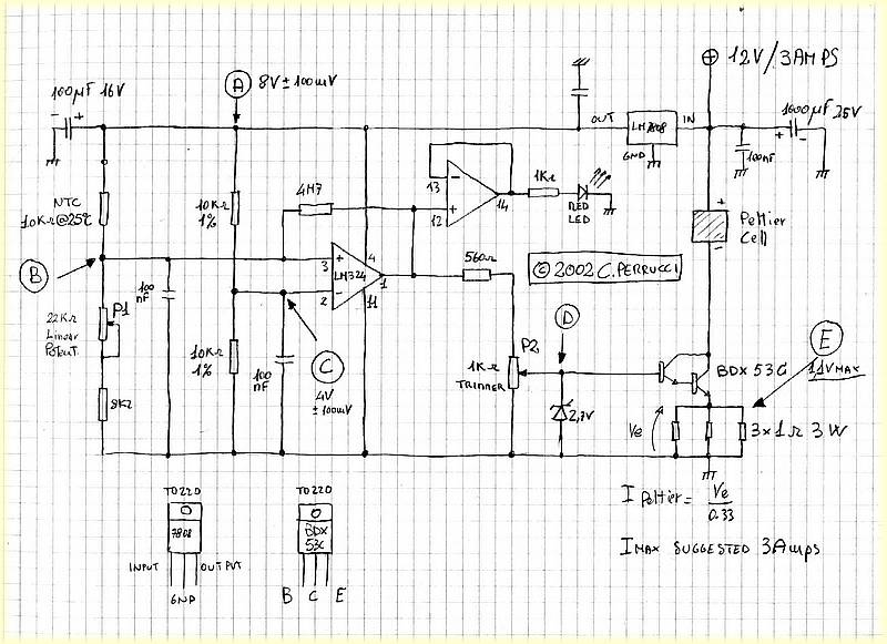
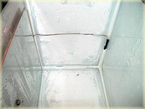
NTC is used for measuring temperature inside the tank.
If voltage applied to the non-inverting input of the comparator is greater than threshold (4V),
output goes to HI logic level (6.5V).
Output voltage is divided by P2 and brought to a simple but reliable pump current. Zener diode clamps voltage to 2.7V limiting current flowing in the
load to 3 Amps maximum.
CALIBRATION PROCEDURE
DO NOT FIT LM324 INTEGRATED CIRCUIT INTO THE SOCKET, DO NOT CONNECT PELTIER AND
NTC.
STEP1
- Solder a 10KOhm (1% Tollerance) between Point A and
B.
NOTE: The above resistor simulates NTC working at 25 degrees.
- Apply a 12V DC power supply to the board.
- Check Point A: 8V +/- 100mV voltage must be present
- Check the presence of 8V +/- 100mv voltage between pin 4
(+Vcc) and 11 (GND) of LM324 socket.
- Check Point C (pin 2 of LM324 socket): 4V +/-
100mV voltage must be present.
- Turn P1 (22KOhm Potentiometer) to read on Point B
(pin 3 of LM324 socket) the value shown in the below table and label
the potentiometer position with the corresponding temperature (indicative):
Voltage on Point B = 4V +/- 50mV 25 Celsius
Voltage on Point B = 4.4V +/- 50mV 20 Celsius
Voltage on Point B = 4.8V +/- 50mV 15 Celsius
Voltage on Point B = 5.2V +/- 50mV 10 Celsius
Voltage on Point B = 5.6V +/- 50mV 5 Celsius
- Turn P1 to the beginning position.
- Remove 10KOhm resistors and connect NTC.
YOU CAN NOW SWITCH OFF THE POWER SUPPLY.
STEP 2
- Ensure that NTC is at room temperature of 25°C or below.
- Fit correctly LM324 Integrated Circuit into the socket.
- Apply a 12V DC power supply to the board.
- Turning P1 you should turn on Red
Led.
- Turn P2 (1 KOhm Trimmer) reading 0 V to Point
D.
- Turn P1 to the beginning position.
YOU CAN NOW SWITCH OFF THE POWER SUPPLY.
STEP3
- Connect a 12V 50/60W Watt lamp from +12V and the Collector of BDX53C Transistor.
- Put a Voltmeter between GND and point E (BDX53C Emitter).
- Apply a 12V DC 5 Amps minimum power supply to the board.
- Turn P1 to light on Red Led.
- Turn P2 to read from 0 to 2.5V on the Voltmeter.
Lamp should turn on and you should control intensity by turning P2.
Turn back P2 to the beginning position.
- Switch off the power supply and disconnect lamp.
NOW YOU ARE SURE THAT CONTROL CIRCUIT IS WORKING AND YOU MAY CONNECT THE PELTIER
CELL.
LAST STEP
- Apply a 12V DC 5 Amps minimum power supply to the board.
- Turn P2 to read up to 1 Volt on the Voltmeter (1.1V Maximum)
NOTE: the current flowing into the Peltier Cell is given by the following formula:
I Peltier= V(Point E) / = 0.33
COMPLETING THE TANK
Mount the Peltier Control Circuit, the fan box and the other parts.
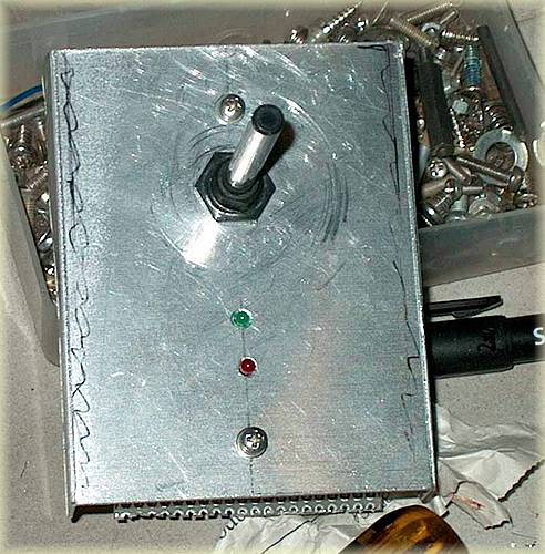

Note that Transistor is mounted with electro-insulating thermo-conductive material. This Transistor if not properly cooled will became very hot.
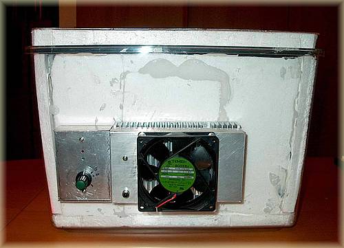
Cooled Tank is now ready for working.