GERMANIA
REICHSMARINE
![]()
![]()
![]()
![]()
![]()
![]()
![]()
![]()
![]()
![]()
![]()
CORAZZATA BISMARCK
NAVE DA BATTAGLIA BISMARCK
BATTLESHIP BISMARCK
SCHLACHTSCIFF KMS BISMARCK
STORIA DEL PROGETTO / HISTORY PROJECT
(Tratto da: "Grandi navi da battaglia tedesche della Seconda Guerra Mondiale" di M.J. Whitley, 1989)
L 'abrogazione unilaterale del trattato di Versailles proclamata da Hitler il 16 marzo 1935 scatenò un fermento di attività
diplomatiche che portarono tre mesi più tardi, il 13 giugno, alla firma dell'Accordo Navale Anglo-Tedesco con cui la Germania si
impegnava a limitare la propria flotta al 35% di quella britannica.
Per la categoria delle corazzate i Tedeschi avevano ora diritto a 184.000 tonnellate, e sottratte le tre Panzerschiff e le due
Sharnhorst, disponevano ancora di 101.000 tonnellate circa per le nuove costruzioni. Restavano tuttavia in vigore le restrizioni del
trattato di Washington del 1922 e della Prima Conferenza Navale di Londra, che imponevano un massimo di 35.000 tonnellate per
il dislocamento delle corazzate. La Germania era perciò libera di costruire tre nuove unità di questa stazza con il tonnellaggio
rimasto.
La Germania tendeva ormai da tempo a non rispettare le norme di Versailles, e già nelle discussioni prelimimari sulla
Schlachtschiff F della primavera del 1934 si era specificato un dislocamento di 35.000 tonnellate.
La richiesta iniziale prevedeva inoltre otto cannoni da 33 cm e dodici da 15 cm in torri binate, sedici bocche da 10,5 cm e i
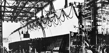
serazzato in costruzione. (IWM) guenti spessori per la corazzatura:
Cintura principale 350 mm (come le D e E)
Prua e poppa 150 mm
Ponte corazzato (orizzontale) 100 mm
.Ponte corazzato (curvatura e
sopra le stive e i timoni) 120 mm
Ponte di coperta 50 mm
Barbette 350 mm
Barbette da 15 cm 150 mm
Torre di contro11o 400 mm
Paratie anti-siluri 60 mm
Paraschegge laterali 60 mm
Ci si rese presto conto che era impossibile entro il limite delle 35.000 tonne11ate con questo tipo di protezioni, quindi la
cintura fu ridotta a 320 mm, la prua a 70 mm e la poppa a 90 mm.
Per la propulsione principale si stavano ancora vagliando le varie proposte, rappresentate nei dettagli dagli schizzi di progetto 3-6.
Per l'autunno del 1934 l'Ufficio Costruzioni aveva calcolato le dimensioni approssimative per un'unità con otto cannoni da 33
cm. con corazza, armamento secondario e antiaereo come quelli delle D e E, e con 30 nodi di velocità. Durante una discussione
del progetto il 2 novembre, si stabilì che per garantire la superiorità sulla
Dànkerque e sulla Strasbourg, oltre che la parità con le corazzate future di altri paesi, occorreva garantire una velocità
massima di 33 nodi, continua di 30 nodi e da crociera di 21 nodi.
Il vice Ammiraglio Guse, capo de11'UfficioGenerale, era contrario a queste cifre e propose rispettivamente 29, 27 e 21 nodi di
velocità; il suo suggerimento fu accolto per i primi due progetti, ma il 26 novembre la velocità massima venne ulteriormente
ridotta a 28 nodi sul miglio misurato, e cioè in condizioni di prova sul
mare a 27 nodi. 11 dislocamento per questo tipo di nave risultò di 37.200
tonnellate.
Il 10 novembre l' Ammiraglio Raeder aveva ribadito che il progetto non doveva in nessun caso eccedere le 35.000
tonnellate e che le dimensioni de11o scafo dovevano adeguarsi ai limiti delle
chiuse, degli attracchi e de]]e strutture portuali esistenti. Le richieste dei militari vennero riesaminate su11a base di questi
ordini, ma mon ridotte, e si ammise che i progetti "crescevano" sempre quando venivano realizzati. Si concluse che era impossibile
ridurre il dislocamento al di sotto de11e 37.200 tonne]]ate, e la cosa fu confermata dai calcoli de11'Ufficio Costruzioni.
il 21 dicembre 1934, su11a base de11e proposte de11'Ufficio Generale avallate
dagli Uffici Armi e Costruzioni, l'Ammiraglio Raeder accettò di:
(a) superare il
limite del dislocamento di un incremento sostanziale delle capacità belliche
(b) tenere in considerazione la propulsione turboelettrica,
(c) ordinare due diversi progetti, uno con quattro torri binate da 33 cm e motori turboelettrici, e uno con turbine a vapore
e quattro torri binate da 35 cm.
Dopo alcuni calcoli, l'Ufficio Costruzioni dichiarò che con le caratteristiche militari richieste nessuno dei due progetti (c)
era realizzabile senza superare il dislocamento previsto, e che i Deusche Werke di Kiel non erano adatti alla costruzione di
queste navi. Il 17 gennaio 1935, una conferenza discusse il rapporto e concluse che la lunghezza degli scali dei cantieri di Kiel o
di Wilhelmshaven non doveva in alcun modo condizionare le dimensioni dello scafo, ribadendo che i limiti massimi erano
quelli delle chiuse e della profondità dei porti tedeschi.
Si discusse anche dell'armamento principale (33 o 35 cm) e si fissò una velocità massima di 28 nodi, che Raeder interpretò
invece come velocità continua generando in seguito dei malintesi su quali fossero i requisiti effettivi dei progetti.
Due giorni dopo, il 19 gennaio, l' Ammiraglio Raeder decise di sviluppare il progetto F a turbina con i cannoni da 35 cm.
Lo spessore della corazzatura fu variato solo per le barbette che diventarono di 350 mm sopra e di 320 mm sotto il ponte di
coperta
La velocità continua massima doveva essere di 28 nodi. Si sapeva che ciò avrebbe fatto superare il limite delle 35.000
tonnellate, ma si raccomandò di chiamarlo sempre il progetto da "35.000 tonnellate". A questo punto il dislocamento delle corazzate
era salito a 39.000 tonnellate, ma le stime più recenti e
accurate i pesi di scafo della Sharnhorst e della Gneisenau rivelarono che anche
questa cifra non bastava a soddisfare le richieste e che occorreva
ridurre ancora parte della corazzatura, il dislocamento poteva essere aumentato
ulteriormente solo a costo e superare il pescaggio, finora considerato massimo,
di 10 ma t :no carico. Nel frattempo, l'approfondimento tecnico dell'attraversamento del canale di Kiel e della scelta di Wilhelmshaven , me base, aveva
stabilito per lo scafo i limiti di 242 m di lunghezza, 36 m di larghezza e 10
m di pescaggio.
Nel
marzo de11935, probabilmente a causa della denuncia I :1 trattato di Versailles,
si cominciò a chiedere l'adozione dei cannoni da 38 cm, possibile solo aumentando
il peso di 1.500 tonnellate e portando quindi il dislocamento a 42.000-42.500
tonnellate. Per evitare una trasgressione eccessiva sopra le 35.000 tonnellate
bisognava ridurre considerevolmente la velocità e/o le protezioni.Il progetto superava già di 6.000 tonnellate i limiti di
Washington e data la
scarsa profondità dei porti tedeschi, l'Ufficio Generale decise di non andare
oltre i cannoni da 35 cm. L 'accesso al bacino più grosso di Wilhelmshaven era
possibile per la nave da 41.000 tonnellate, con 9,25 m di pescaggio armata
I
bacini di Wllhelmshaven erano lunghi 250 m. e profondi 10 m, larghezza
era di 38 m per quello nord e di 33 m per quello sud. L'11 aprile 1937;
dopo aver consultato i capi dei partiti principali, Raeder decise che
il dislocamento avrebbe ora dovuto ;ere di 41.000 tonnellate e l'armamento
principale di quattro torri binate da 35 cm, con l'intenzione di ordinare la nave
alla Ohm & Voss di Amburgo l'1 aprile dell'anno seguente. Se il vertice
navale delle maggiori potenze allora in corso l'avesse permesso, si sarebbe
potuto portare il calibro dei cannoni a 38 cm n altri sei mesi di lavori, e il 9
maggio 1935 Raeder rese ufficia- questo aumento per l'armamento principale.
Nel
frattempo l'Ufficio Costruzioni aveva studiato quattro alternative per i motori
principali:
(a)
Turbine a vapore ad alta pressione con dodici caldaie distribuite in sei sale a
proravia delle sale macchine.
(b)
Come (a), ma con le caldaie in tre sale a proravia delle sale macchine.
(Soluzione preferita dall'Ufficio Costruzioni).
(c)
Come (b), ma con una sala caldaie fra le sale macchine. (d) Propulsione
turboelettrica. (Scartata per motivi di peso). Queste quattro soluzioni e le
diverse proposte per l'armamento secondario, compreso l'uso di casematte,
vennero rapprentate dettagliatamente negli schizzi A3-A6, mentre gli schizzi
7-A9 mostravano varie dislocazioni per i generatori (versioni E) e per le torri
di poppa dei progetti con le casematte da 25 cm.
L
'Entwurf A2 era un progetto a turbina triassiale con 15.000 HP per 28 nodi dì
velocità. Poteva stivare 8.000 tonnellate di carburante, aveva una lunghezza totale di 245,2 m (241,5 m al galleggiamento)
e una larghezza di 36 m. L'armamento secondario era di quattro bocche binate da
15 cm in piazzole C734 più altre quattro in postazioni singole MPL C/20. La
Entwurf A3 aveva dodici cannoni C/28 da 15 cm, tutti in casematte, mentre la A4
aveva tutti i suoi 15 cm in affusti binati LC/34 di cui uno centrale sulla
sovrastruttura del ponte. L 'Entwurf A5 era l' A2 a propulsione turboelettrica.
Le
casematte erano già obsolete, sorprende quindi che abbia- no suscitato accese
discussioni; alla fine si decise comunque di migliorare le protezioni costruendo
una fortificazione chiusa con una corazza da 150 mm fra la cintura principale e
il ponte di coperta e di montare in torri l'armamento secondario. Diversamente
dalle casematte, questa cittadella non avrebbe corso il rischio di venir
investita dalle ondate, e se ne proposero diverse versioni: una fortificazione
che arrivava a racchiudere sia le torri che i relativi depositi, altre versioni
limitate alle torri A e D e una ristretta fra le torri B e C.
Il
7 giugno 1935 un'altra conferenza lanciò varie proposte per l'armamento
secondario e continuò la discussione sui motori principali. A questo punto, le
prestazioni incoraggianti dei moto- ri turbo elettrici del transatlantico Lloyd
Sharnhorst rimise in gioco questo tipo di propulsione anche se comportava 600
tonnella- te di peso in più e nonostante le prudenti riserve dell'Ufficio
Costruzioni. Raeder decise che non si dovevano aumentare le misure già
approvate o il dislocamento e si dichiarò soddisfatto della corazzatura.
Caldeggiava l'installazione in torri di tutto I'arma- mento secondario e la
compensazione del peso dei motori turboelettrici con tagli in altri settori.
Il 23 agosto, l'Ufficio Costruzioni consegnò a Raeder lo schizzo di progetto A13, un modello turboelettrico triassiale che ottenne l'approvazione dell'ammirag1io. Bisognava ancora definire qualche particolare come la contraerea, la forma del ponte, le postazioni di comando e l'attrezzatura aerea.
L'Algemeineamt chiese e ottenne il raddoppiamento degli otto pezzi da 3,7 cm in affusti binati, oltre alla riduzione della cittadella allo spazio fra le torri B e C per migliorarne I'abitabilità. Un successivo riesame dei progetti dimostrò che era possibile ricavare degli spazi per gli uomini fuori dalle aree più corazzate, e la fortificazione venne riportata alle dimensioni di partenza (con decisione del 23 gennaio 1936).
Contemporaneamente lo spessore delle barbette all'interno della cittadella fu ridotto a 220 mm, e parte del ponte corazza- to da 100 a 80 mm. Le protezioni vennero ulteriormente migliorate con dei paraschegge da 20 mm sul ponte di manovra, aumentando a 95 mm il ponte corazzato sopra le stive principali e prolungando fino al ponte di manovra le paratie corazzare terminali 32 e 202,7. Su suggerimento degli Uffici Armi e Costruzioni, il 23 novembre 1935 Raeder accettò di eliminare la rastremazione superiore della cintura di corazza e di ridurla a 300 mm di spessore.
Nell'ottobre
1935, l'impostazione della F era prevista per l'1 luglio 1936 e si sperò di
poter anticipare i tempi finche non sorsero delle complicazioni politiche che
spinsero ad affrettare il completamento della nave per averla in servizio entro
il 1° ottobre
1939,
due mesi prima della data prevista. La G era stata assegnata allo scalo della
Sharnhorst che non era abbastanza lungo; come 1 per la Gneisenau si sarebbe
quindi avviata provvisoriamente 1 un'impostazione parziale della chiglia il1 °
gennaio 1937, quattro mesi prima del previsto, con completamento il1 ° febbraio
1940.
Nel giugno 1936, l'Ufficio Costruzioni si pronunciò definitivamente contro la propulsione turboelettrica e consigliò a Reader le turbine a vapore. Il 6 giugno Raeder accettò questo suggerimento che comportava una notevole revisione dei calcoli e dei disegni come era già avvenuto per le Panzerschiff D e E. Il cambio di propulsione non fece diminuire il dislocamento perché si colse l'opportunità per riportare la cintura principale da 300 a 320 mm, ma la scelta della saldatura invece dei bulloni per la corazza del ponte di coperta fece risparmiare del peso che servì ad aumentare il ponte sopra le stive da 95 a 100 mm e nella curvatura da 110 a 120 mm. Dal dicembre 1936 non fu più possibile inspessire ulteriormente il ponte corazzato perché le piastre erano ormai laminate.
(Taken from "Great German Battleships of World War II" by MJ Whitley, 1989)
The unilateral abrogation of the Treaty of Versailles by Hitler proclaimed March
16, 1935 unleashed a flurry of diplomatic activity that led to three months
later, on June 13, the signing of the Anglo-German Naval Academy in which
Germany agreed to limit the its fleet to 35% of the UK.
For the category of the battleships, the Germans were now entitled to 184,000
tons and subtracted the two and three Panzerschiff
Sharnhorst, still has 101,000 tons for new construction. However, restrictions
remained in force of the Treaty of Washington of 1922 and the First London Naval
Conference, which imposed a maximum of 35,000 tonnes for the deployment of the
battleships.. Germany was therefore free to build three new units of this size
with the remaining tonnage.
Germany has long tended to disregard the rules of Versailles, and already in
discussions on the preliminaries Schlachtschiff F in the spring of 1934 he was
given a displacement of 35,000 tons.
The original request also included eight guns and twelve 33 cm by 15 cm in twin
turrets, sixteen mouths to 10.5 cm and Serazzi under construction.
(IWM) armor for the following thicknesses:
350 mm main belt (such as D and E)
Fore and aft 150 mm
Armored deck (horizontal) 100 mm
Armored deck (bending and 120 mm above the holds and rudders) 120 mm
50 mm deck
Barbette 350 mm
Barbette of 15 cm 150 mm
Tower contro11o 400 mm
60 mm anti-torpedo bulkhead
Shield side 60 mm
We soon realized that was impossible within the limits of the 35,000 tonne11ate
with this type of protection, so the belt was reduced to 320 mm, 70 mm in the
bow and stern to 90 mm.
For main propulsion were still considering the various proposals, represented by
the sketches in the details of the project 3-6.
By autumn 1934, the Construction Office had estimated the approximate size for a
unit with eight 33 cm guns with armor, weapons and bomb the secondary as those
of D and E, and with a speed of 30 knots.
During a discussion of the project on November 2, moved in order to ensure
superiority over Dànkerque and Strasbourg, as well as parity with the
battleships future of other countries, it was necessary to ensure a maximum
speed of 33 knots, 30 knots, and continues to cruise of 21 knots.
The vice admiral Guse, head de11'UfficioGenerale, was opposed to these figures
and suggested that respectively 29, 27 and 21 knots, and his suggestion was
accepted for the first two projects, but on November 26 the maximum speed was
further reduced to 28 nodes on the measured mile, and that under test conditions
on the sea at 27 knots.
displacement for this type of vessel is of 37,200 tons.
On 10 November the 'Admiral Raeder had insisted that the project was in no case
exceed 35,000 tons and that the size DE11 hull had to adapt to the limits of the
locks, moorings and the de]] and existing port facilities.
The demands of the military were reviewed su11a basis of these orders, but small world, and it was admitted that the projects "grew" more and when they were made.
It was concluded that it was impossible to reduce the displacement of 37,200 tonne in DE11]] ed, and it was confirmed by calculations de11'Ufficio Construction. December 21, 1934, according su11a DE11 de11'Ufficio proposals endorsed by the General Offices and Buildings Arms, Admiral Raeder agreed to:
(A) exceed the limit of displacement of a substantial increase in warfighting
capabilities
(B) take into account the propulsion turboelettrica,
(C) give two different projects, one with four twin turrets with 33 cm and
turboelettrici engines, steam turbines and one with twin towers and four 35-cm.
. After some calculations, the Office of Construction said that the military
characteristics required neither of the two projects (c) was achievable without
exceeding the expected displacement, and that Deusch Werke of Kiel were not
suitable for the construction of these vessels.
On 17 January 1935, a conference discussed the report and concluded that the
length of the ports of Kiel and Wilhelmshaven sites should not in any way affect
the size of the boat, insisting that the ceilings were those of the locks and
depth of German ports .
He also discussed the main armament (33 or 35 cm) and fixed a maximum speed of
28 knots, which Raeder interpreted instead as a constant speed generating as a
result of misunderstandings about what were the actual requirements of the
projects. Due giorni dopo, il 19 gennaio, l' Ammiraglio Raeder decise di
sviluppare il progetto F a turbina con i cannoni da 35 cm. Two days later, on
January 19, the 'Admiral Raeder decided to develop the F-turbine project with 35
cm guns.
The thickness of armor was changed only for the painters who became of over 350
mm and 320 mm below the deck
The maximum continuous speed of 28 knots had to be.
We knew that this would exceed the limit of 35,000 tons, but is always recommended to call the project "35,000 tons." At this point the displacement of the battleships had risen to 39,000 tonnes, but the most recent and accurate estimates of the weight of the hull and Gneisenau Sharnhorst revealed that even this figure was not enough to satisfy the requests and that it was necessary to further reduce the armor, the displacement could be increased further only at the cost and pass the draft, so far as the maximum, but 10-t: no load.
Meanwhile, the technical study of crossing the Kiel Canal and the choice of Wilhelmshaven, my base, had established limits for the hull of 242 m long, 36 m wide and 10 m draft.
De11935 in March, probably because of the complaint: a Treaty of Versailles, began to pursue the adoption of the guns of 38 cm, possible only by increasing the weight of 1,500 tons and bringing the 42,000 to 42,500 tons displacement.
To avoid an excessive infringement on the 35,000 tonnes needed to significantly reduce the speed and / or project protezioni.Il already exceeded the limit of 6,000 tonnes of Washington and given the shallowness of the German ports, the General Office decided not to go beyond the 35 cm guns.
The access to the largest pool of Wilhelmshaven was possible to ship 41,000 tons, armed with 9.25 m draft mouths to 35 cm, but not one with the guns of 38 cm and then with 9.40 m draft.
. If you were reduced to compensate for the armor, the ship would become lower than the Strasbourg; still ran to the discussion of the following proposed and the thickness of the protections.
The ponds were long Wllhelmshaven 250 m. width was 38 m to the north and 33 m to the south. On April 11, 1937, after consulting the leaders of major parties, Raeder decided that the deployment would now due; ages of 41,000 tonnes and The main armament of four twin turrets with 35 cm, with the intention to order the ship to the Ohm & Voss in Hamburg on April 1 next year.
If the summit of the major naval powers had allowed the then current, he could bring the caliber of the guns to 38 cm n six months of work, and May 9, 1935 Raeder made offi-this increase for the main armament.
Meanwhile, the office building had studied four alternatives for main engines:
(A) high-pressure steam turbines with twelve boilers distributed in six rooms of the forward engine room.
(B) As (a), but the boilers in three rooms of the forward engine room. (Solution preferred by construction).
(C) As (b), but with a boiler room in the engine rooms.
(D) Propulsion turboelettrica. (Discarded for reasons of weight).
These four solutions and the different proposals for the secondary armament, including the use of pillboxes, were detailed in sketches rapprentate A3-A6, while the 7-A9 sketches showing various locations for the generators (and versions) and the towers stern of the projects with the casemates of 25 cm.
The Entwurf A2 was a tri-axial turbine design with 15,000 HP to 28 knots.
He could stow 8,000 tons of fuel, had a total length of 245.2 m (241.5 m at the waterline) and a width of 36 m. The secondary armament was four ports coupled by 15 cm in places other than C734 in four locations each MPL C/20. The A3 had twelve guns Entwurf C/28 15 cm, all in the casemates, while the A4 was 15 cm in all its carriages in a central binary LC/34 on the superstructure of the bridge.
Entwurf A5 was the' A2 propelled turboelettrica.
The casemates were already obsolete, surprisingly, has generated heated debate-no, eventually opted to improve the protections built a fort with a closed shell of 150 mm between the main belt and the bridge deck and towers installed in the 'secondary armament..
Unlike the casemates, this town would not have taken the risk of being hit by waves, and he proposed several versions: a fort that came to encompass both the towers that its stores, other versions limited to towers A and D and a small one Towers B and C.
. On June 7, 1935 another conference launched a number of proposals for the secondary armament and continued the discussion on the main engines.
At this point, the encouraging performance of the movement re-turbo electric liner Sharnhorst Lloyd went back into play this type of propulsion even if you meant 600 tons in weight and more cautious despite the reservations of the Office Building.
Raeder decided that no increase had already approved measures or the displacement and declared himself satisfied with the armor.
Advocated the installation of towers in all secondary and chin-hammer is the compensation of the weight of the engines turboelettrici with cuts in other areas.
On 23 August, the office building to Raeder gave a sketch of the A13 project, a model which obtained the approval turboelettrico triaxial dell'ammirag1io. You still need to define some details such as the anti, the shape of the deck the control stations and equipment by air.
The Algemeineamt sought and obtained a doubling of the eight pieces of 3.7 cm in carriages combined, in addition to the reduction of the citadel to the space between the towers B and C to improve the abitability.
A subsequent review of the projects showed that it was possible to obtain space for the men out from the areas most battleships, and the fortification was reported to the size of departure (a decision of January 23, 1936).
At the same time the thickness of the painters in the town was reduced to 220 mm, and the bridge-to armor from 100 to 80 mm. The guards were further enhanced with the shield of 20 mm on the deck of maneuver, increasing to 95 mm above the armored deck holds the key to the bridge and extending operating the terminals 32 and 202.7 bulkhead armor.
At the suggestion of Weapons and Construction Office, November 23, 1935 Raeder agreed to remove the top of taper belt armor and reduce it to 300 mm thick.
In October 1935, setting the F was scheduled for July 1, 1936 and it was hoped to be able to anticipate the time until the political complications arose that led to hasten the completion of the ship to have it operational by October 1
1939, two months before the scheduled date.
The G was assigned to the call of Sharnhorst that it was not long enough, as for a Safe Boot Gneisenau would then approach a part of the keel IL1 January 1937, four months ahead of schedule, with completion IL1 February 1940.
In June 1936, the Construction Office ruled definitively against the propulsion and advised turboelettrica Reader steam turbines.
On June 6, Raeder accept this suggestion procedure that involves a substantial revision of the calculations and drawings as was the case for the Panzerschiff D and E.
The rate of propulsion did not decrease the displacement because it took the opportunity to bring the main belt between 300 and 320 mm, but the choice of the bolts instead of welding to the shell of the deck he used to save weight increase bridge over the holds from 95 to 100 mm and the curvature from 110 to 120 mm.
Since December 1936 it was no longer possible to further thicken the bridge hé armor because the plates were already rolled.
CORAZZATA BISMARCK /STORIA E CARATTERISTICHE TECNICHE / HISTORY
CORAZZATA BISMARCK / BATTLESHIPS BISMARCK
CACCIA ALLA BISMARCK / THE HUNTING OF THE BISMARCK
BATTAGLIE NAVALI / NAVAL BATTLES
NAVI DA GUERRA /WARSHIPS AND BATTLESHIPS