
This is the first system that I decided to build to finally fly without using the mouse and the keyboard (to set the autopilot parameters at least).
The structure is made by light wood (5 mm thin) and the whole module is composed so far by:
- 2 8x2 (8 characters, 2 rows) LCD displays HD44780 compatible, green positive backlight
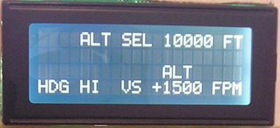
- 1 20x4 LCD display HD44780 compatible, white negative backlight
- 6 CTS-288 encoders (type "grey") with pushbutton
- 1 Master Card
- 9 micro-buttons (the type you can find inside a joystick)
- 2 lever buttons
- 2 rotary switches (12 positions)
(The Master Card and the encoders were bought at Opencockpits)
Actually the module is not yet complete, some hardware is missing but with the components listed above you can operate the autopilot using most of its functions.
The biggest work has been developing the software that manages the module.
I had to develop a specific software due to the complexity of the autopilot logic, using as model several ATR panels found on the net and according with some information I collected in various discussion forums (I thank all the people who gave me those infos).
Now let's go into details.
I already explaned how to drive a LCD display through the parallel port so if you need a "memory refresh" I suggest you to read the "LCD" section of this site.
The only thing that is different is that I drive 3 displays using 1 parallel port in the following way (refer to the wiring scheme in the "LCD" section):
- pin 16 --> Enable pin display 20x2 (active high)
- pin 17 --> Enable pin display 8x2 (active low) NAV1
- pin 14 --> Enable pin display 8x2 (active low) NAV2
RS pins are connected together to the pin 1 of the parallel port, RW pins are connected together to GND (then you can't use the "user defined characters" feature of the HD44780).
Let's spend some word about the encoder CTS-288.
It's a 2 bit encoder of type "grey" with pushbutton...what does that mean?
2 bit means (obviously) that its outputs can have 4 possible combinations and "type Gray" that the outputs follow these scheme: 00 01 11 10 rotating the shaft in one way, the sequence is "turned back" rotating the shaft in the opposite way.
Thus considering the above sequence, it's easy to understand what is the rotation direction of the encoder.