Vacuum
diode
Models
& PSpice
Simulations
by Stefano Perugini
This article appeared originally in Glass Audio, Vol.10,Nr. 4, 1998.
The
renewed interest in the thermionic technology applied to the audio is pushing
the most sensitive designers to use, widely, the modern tools of circuit
simulation SPICE-oriented, in the convincement that the best sonic results to be
gotten with a deep circuit optimization and not simply making use of the most
expensive component. An ulterior big advantage is given by the facility wich is
possible to experiment unusual and effective solutions saving up time and money
contemporarily.
In this article I focus the attention in the creation of a very simple
but accurate vacuum diode model in the conviction that the correct realization
of an audio amplifier cannot be separated from the correct realization of
associate power-supply. Moreover many people are convinced that the best sonic
results could be gotten just turning to the vacuum diode as rectifier element.
Nevertheless the use of such devices presents some problems; in fact it is
necessary to check by calculations often dull and not very careful, several
parameters as the repetitive peak current,
the hot-switching current, the maximum
inverse voltage and so on, otherwise it is possible to lead the device to a
premature death. On the contrary if you resort to the circuit simulation, on the
condition that you have accurate models, you can overcome the optimization phase
in the virtual world, totally, and go out only to effect the inevitable
micro-adaptations and therefore build the real object.
At the end of this article I will show the goodness of the mathematical model used by comparing it with a real situation, that is comparing the results gotten by measurements on a simple power supply phisically realized, with the results gotten by the same simulated power supply.
In the "sacred texts" the
equation brought for describing the operation of the diode is the well note
Child-Langmuir's Law:
Ip= K*Vp1.5
(1);
where:
Ip
is the current that flows in the diode;
Vp
is the anode to cathode voltage;
K
is a costant said perveance.
You
can see the perveance as the digital
imprint or the genetic code of the diode because in (1) it constitues the only
parameter able to differentiate the multiplicity of the diodes.
Besides the Child-Langmuir's Law is a phenomenological equation, that is
derived on physical considerations grounds.
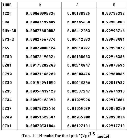
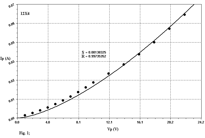
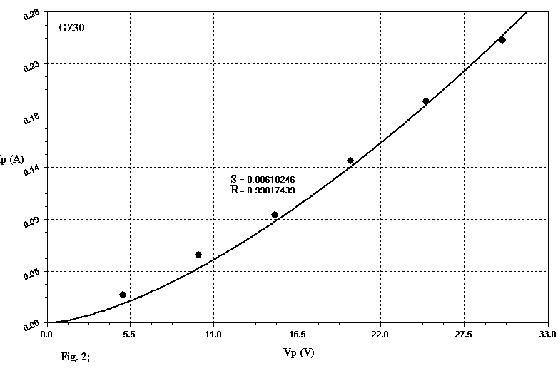
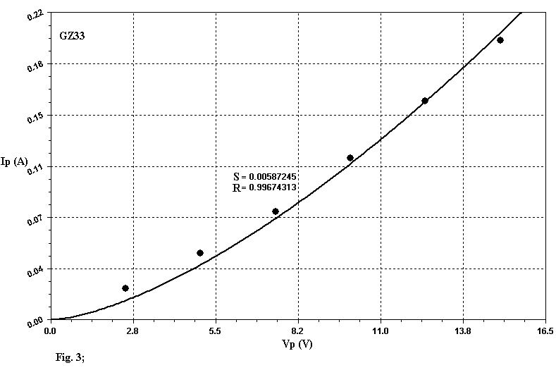
If we use this equation to apply the Least Square Method (LSM) with linear regression to the set of experimental data extracted by the Data-Sheets it is difficult to get a good fitting, as you can see by examining Table 1. In this table S and R represent the Standard Error and the Correlation Coefficient respectively. A perfect fitting is gotten when R is equal to 1. The good values of the Correlation Coefficient R brought in Table 1 must not deceive you, since R is a paramenter of global evaluation and lower values to 0.998 cannot be thought satisfactory as the graphs of the Figg. 1, 2, 3 related to the diodes 12X4, GZ30, GZ33 show, in wich the model introduces, locally, marked deviations. In this graphs the "small black balls" represent the average data extracted from Data-Sheets. In my opinion this model well represent only tubes like 5U4 and GZ40: you can think of them as perfect diodes (although not ideal !). In all the other cases the results can be improved so to get nearest simulations to the reality. The apparent redundance in Table 1 and those following where is present either 12X4 or EZ90/6X4 will be clarified later.
Improvement
You can already get a large improvement by varying the exponent of the
equation (1). This leads to the following expression:
Ip= K*VpA.
Now
use this equation, but modified in the following way:
Ip= K*(Vp+EPS)A
(2)
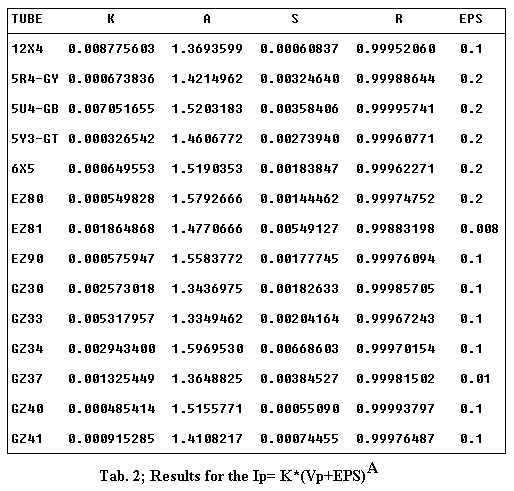
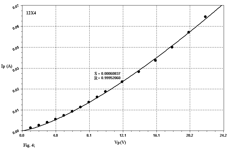
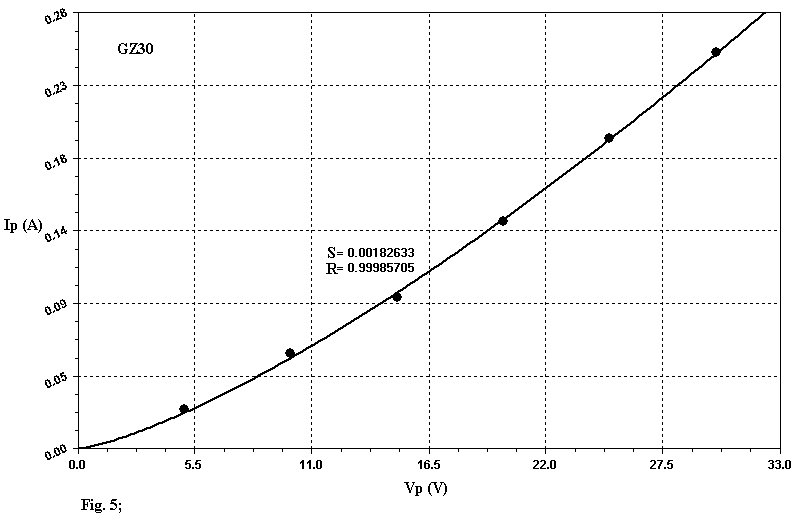
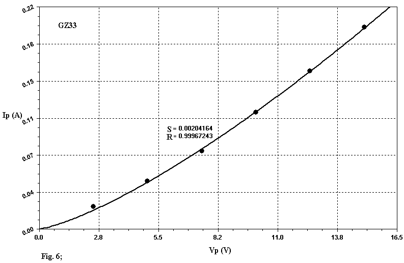
to apply LSM to the set of experimental data. The results of this procedure have quoted in Table 2. EPS represents a parameter that can be manually fixed (typical values are 0.1, 0.2) used to guarantee a better convergence of the algorithm. If you compare the Correlation Coefficient of the Table 1 and 2, you can note a real amelioration, underlined subsequently by the new graphic representations of the tubes 12X4, GZ30, GZ33 related in Figg. 4, 5, 6. Futhermore the examination of Table 2 reveals that the real diode is subjugated by the 3/2 power law only in few cases.
Finally
you can get an even better fitting if you use the following equation:
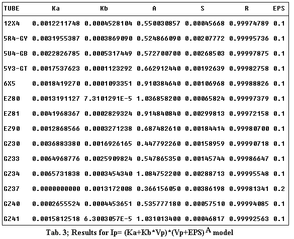
Ip= (Ka+Kb*Vp)*(Vp+EPS)A
(3).
The equation (3) differs from (2) because a linear variation to the perveance has been attributed with respect to Vp. The application of LSM with linear regression leads to the data in Table 3. You can get further short improvement margins using more sophisticated mathematical models although this injuries simplicity and brings larger problems of convergence in simulations.
SPICE
Now you can use the data in Table 3 to build the SPICE model of the diode.
After the excellent articles by Raynolds [2], Marshall [3] and Koren [4], I don't
think you will find any difficulty to understand the code in Table 4. The only
required operation is to use the information in Table 3 and complete the code in
Table 4 on the grounds of the selected diode.
.SUBCKT
tubename P K
+
PARAMS Ka=
Kb=
+
A=
Eps=
E1
1
0
VALUE = {Ka + Kb
* V(P,K)}
RE1
1
0
1G
E2
2
0
VALUE = {V(P,K) + EPS}
RE2
2
0
1G
G1
P
K
VALUE = {V(1)/2 * (PWR(V(2), A)
+ PWRS(V(2), A))}
RPK
P
K
1MEG
*
CPK P
K
.5n
.ENDS
(*)
CPK can replace RPK in case of serious convergence problems.
Tab. 4
How
use this models
The first reason that can push you to look for an accurate model of vacuum diode is that, you can determine, when the device is used as a rectifier, a series of parameters whose exact evaluation can be either difficult or inaccurate as for istance the repetitive peak current, the hot-switching current, the output impedance etc. Besides the SPICE model you need further informations to place the device in safety areas. These informations are graphically available in Data-Sheets Rating Charts. In my opinion the Radiotron Designer's Handbook magistrally deals with the subject as it faces the whole problem list merely in engineering terms and therefore with calculations and formulae just finalized to the solution of actual situation. Other texts I know lack suitable depth or face the subject in a too academic way not enough finalized to the solution of real problems. On the contrary in the Radiotron's by fast procedures it is possible plan power supplies with both condenser input filter and choke input one. Unfortunately the accuracy, especially in the evaluation of the impulsive currents, is not high but this is due to the use of purposely approximate formulae to have agile calculation that at the time were made by the hand. Besides the book introduces two levels of approximation if you have complete data or not.
In
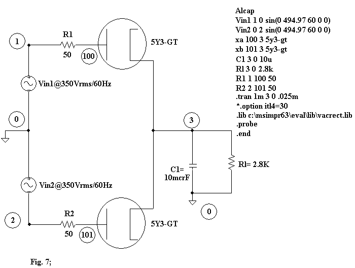
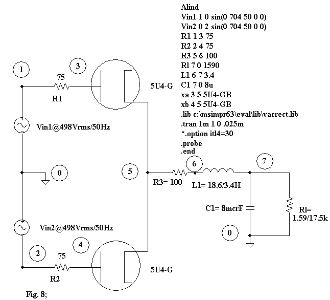
Figg. 7 and 8 I have brought two hypotheses of power supply with condenser and
choke input filter respectively together with their SPICE codes related to
present examples beginning from the pages 1174 and
1183 of the Radiotron Designer's
Handbook. The resistances R1 and R2 are the total
effective plate supply impedance per plate and they represent the impedances
brought to every secondary winding according to the formula:
Rs= Rsec + N2
* Rpri;
where:
N=
Voltage ratio of transformer at no load (primary to half secondary in
case of full-wave rectification);
Rpri=
Resistance of primary winding in ohms;
Rsec=
Resistance of secondary windind in ohms (or half secondary in case
of full-wave
rectification;
Rs=
total effective plate supply impedance per plate.
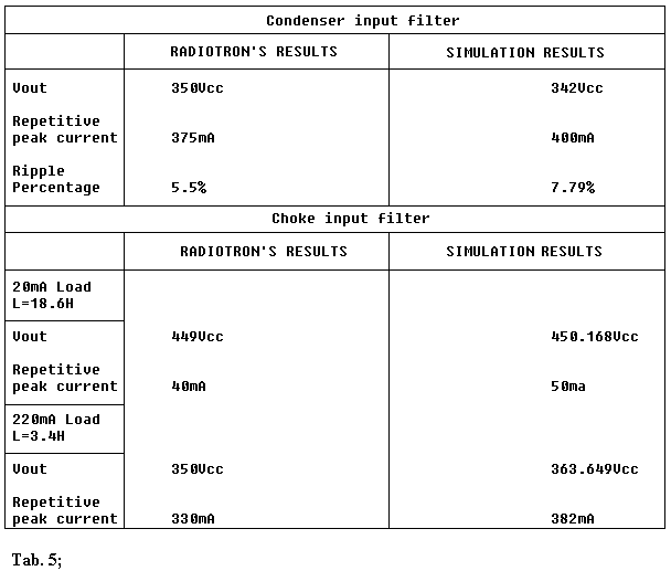
In Table 5 I show a comparison between manual calculations (as brought in the Radiotron's) and simulations. The more meaningful graphic representations of such simulations are brought in Figg 9, 10, 11.
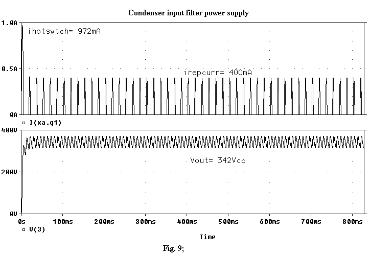
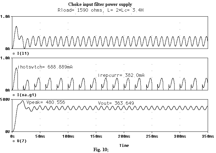
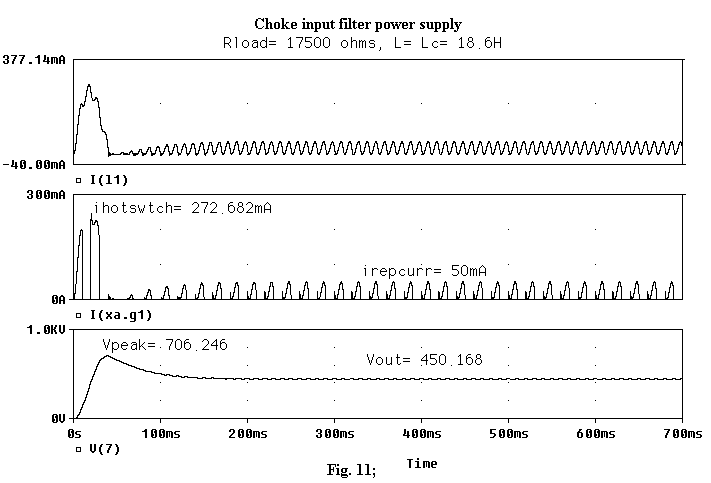
As
you can observe in Fig. 9 it is rather easy to overcome the limits related to
the impulsive currents also with small input condensers therefore their
capacitive value has to be valued very attentively. Besides Fig. 11 reveals that
the swinging choke calculus is not very accurate.
An actual comparison
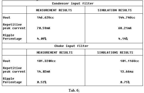
In Table 6 I present the results of two simple power supplies with
condenser and choke input filter respectively. Schematics are the same of Figs.
9 and 10 but with the following differences:
Vin1,
Vin2@120Vrms;
R1=
R2= 6.8 ohm;
L1=
30H in choke input filter power supply;
C1=
8.10 mcrF;
Rl=
10.16K;
12X4
vacuum-diode.
The 12X4 SPICE model whose
parameter have brought in line 1 of Table 3 have been drawn just from the real
diode used for the construction of two power supplies (here explained the reason
for the apparent redundance in Tabb. 1, 2, 3). So here I won't make a comparison
on the grounds of a model drawn from the average characteristics, but with
reference to a Sylvania's 12X4 sample.
The utmost closeness of the numerical results in Table 6, makes me rather
optimist about the validity of the implemented model; to the small differences
that you can recognize, partly contribute also the errors of the measurement
process in real world.
Conclusion
I hope this article can add a small wedge to the big mosaic of the
circuit simulation applied to vacuum tube amplifiers. I believe the thermionic
technology applied to the audio has not yet totally expressed its real potential.
The evidence is given by modern formulation designs wich, often join even in
concepts going back to the dawning of electronics (as well as harmonic
cancellation, feed-forward, tansformer coupling, choke input filter etc.), can
produce sonic results higher than the crowd of Williamson-like amplifiers.
References:
|
[1] |
Charles Rydel |
SIMULATION OF ELECTRON TUBES WITH SPICE", AES preprint 3887 (G-2), 98th AES Convention, Paris 1995; |
|
[2] |
Scott Reynolds |
VACUUM TUBE MODELS FOR PSPICE SIMULATIONS, GLASS AUDIO n. 4, 1993 |
|
[3] |
W. Marshall Leach, Jr |
SPICE MODELS FOR VACUUM TUBE AMPLIFIERS, JAES March 1995 |
|
[4] |
Norman Koren |
IMPROVED VT MODELS FOR SPICE SIMULATION, GLASS AUDIO, N. 5 1996 |
|
[5] |
F. Langford-Smith |
Radiotron Designer's Handbook, 4th Ed. 1953 |
|
[6] |
Piotr Mikolajczyk Bohdan Paszkowski |
Universal Electronic VadeMecum |
|
What did you
think of this article? |