|
|
Theory
High
transconductance vacuum tubes are strange animals, with electrical and
mechanical challenges fully surpassed only at the end of the western thermionic
technology parabola.
But....what’s their
physical structure?
In
Fig. 1 you can see the internal section of a triode with planar electrodes [1].

For this geometry, complex calculi show [2]:
 (1)
(1)
 (2)
(2)
where:
m
Gain
Coefficient;
n
Grid
wires/cm;
a
Cathode to Grid distance (cm);
b
Grid
to Plate distance (cm);
R
Grid
Wire Radius;
Eg
Grid
Voltage;
Ep
Plate Voltage;
Jp
Plate
current density.
In a triode the transconductance, gm is given by:

Since
![]() (where DS
is the emitting surface area) from
eq. 2 you obtain:
(where DS
is the emitting surface area) from
eq. 2 you obtain:
 (3)
(3)
The
equations (1) and (3) are fundamental in the design of triodes (and particularly
for the high gm class).

The Fig. 2 displays
the transconductance gm and the m
factor versus the grid to cathode distance a. The graph
refers to the Russian triode 6C45-PE
but the trend is common for similar triodes (such 6H30, 3A167M, WE437A, ....).
You can observe that gm increases when a decreases.
Also the m
factor slope is affected by a (since a+b is constant)
but can be changed by the geometrical factors in eq. (1) as n and/or R.
Fig. (2) shows a
strong dependance of gm with respect to plate current (indirectly
shown in the graph with Ep=cost and Eg=(-2..0)V)
more marked in the low region of
a values.
Here you have a
classical cost/benefit problem since the reduction of the distance a
causing an increase of gm
(the benefit), submit this parameter to the caprices of plate current strongly
(the cost).
The reduced
dimensions (mechanically faced with non-standard building as frame grid
structure) are the main source of the electrical limits in this tube typology:
a)
Microphonicity;
b)
Self -Oscillating Tendencies;
c)
High Parasitics;
d)
Mismatching.
The
audio designer must manage this drawbacks properly for succesful results.
Applications
The
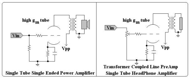
Fig. 3 shows the basic schematics you can use as:
a)
Transformer Coupled Line Amplifier;
b)
Single Tube Power Amplifier;
c)
HeadPhone Amplifier.

For this
applications the best results are obtained with triodes having
high the parameter
s
= gm m.
(4)

An high value in the s parameter reduces the input voltage swing and optmizes the transformer turn ratio for a low output impedance with good current capabilities and high damping factors.

High
s
tubes are useful also in the design of Two-Stage Single Ended
Amplifiers designed thinking to tubes as 211, 845, 300B,
SV-572-XX....and deserve nice surprises in the design of Low Power OTL
amplifiers.
The
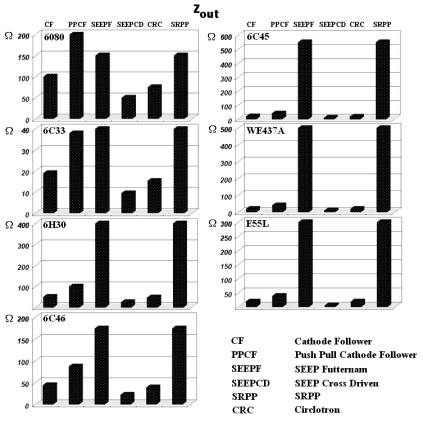
essential requirement for an OTL amplifier is a low open-loop output impedance.
The utilization of low rp
tubes appers as an irrunciable requirement but you can obtain excellent
results also with high s tubes. In fact
the excellent performances in term of Zout for the 6C33 triode (s=0.128)
can be obtained and surpassed with other tubes as 6C45-PE
(s=2.34) and E55L (in pseudotriode mode, s=1.5),
Fig. 6.

Amplifiers
designed around high gm, high s tubes
present obvious advtages in term of noise, gain and bandwidth. In a triode in
fact the Equivalent Noise Resistance, req is given by:
![]()
while
for a common cathode amplifier you have:

where:
Ao Gain
GBW Unity Gain Frequency.


Conclusions
High gm, high s tubes present a wide spectrum of opportunity but also drawbacks
derivated by their intrinsic nature. The variability in the electrical
parameters, but also microphonicity and self oscillating phenomena must be
evaluated with care by calculi, simulations and prototyping .
References:
[1] W.G. Dow,
Fundamentals of Engineering Electronics,
John Wiley & Sons 7th Rep. 1948.
[2] Kusunose, Quziro,
Calculation of Characteristics and the Design of Triodes,
Proc.
I.R.E. , 17, 1706, Oct. 1929.
|
What did you
think of this article? |