Cascade
Stages
|
A common-cathode triode stage exibits an harmonic spectrum decreasing (in a monotonic way) with the frequency and the contribution furnished from even harmonics (particularly the second one) is preponderant. A similar pentode stage presents a wider spectrum and therefore a general increment in the THD values and a greater contribution furnished from odd harmonics. These two different behaviours between triodes and pentodes in the common-cathode configuration could be easily justified by observing that the mutual dynamic characteristic (the true entity that characterizes in an unambiguous manner the non linear behaviour of any amplifier stage), is easily referable to 2nd and 3rd geometric curve for triodes and pentodes rispectively as the Fig. 1, extracted from Radiotron Designer’s Handbook, it puts clearly in evidence [2]. This different behaviour from the two classes of thermionic devices more used in the amplification technique surely plays a role in favor of triodes since even harmonics are simpler to reduce. In fact, when correctly implemented, triode stages with HCT can easily exhibit very low values in the T.H.D. if phase distortions are negligible. |
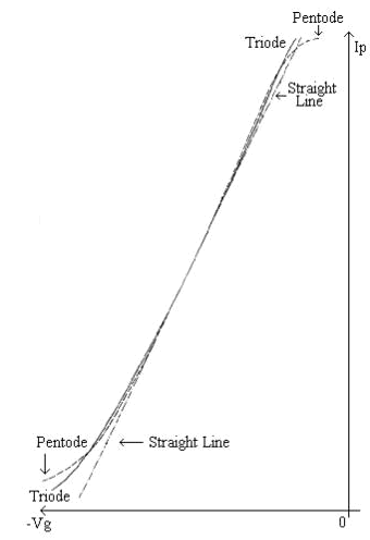
Fig.
1
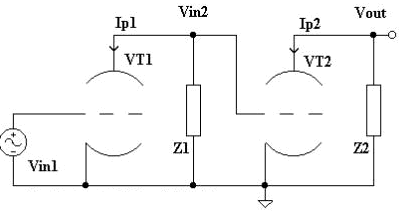
Fig. 2
In the signal domain a
triodes cascade stage is reproduced
in Fig.2.This schematic can represent most of the circuits that you can meet really, Figg. 3-6.
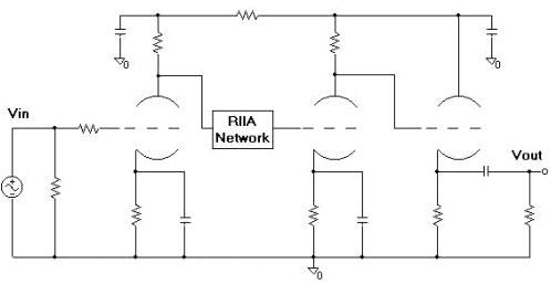
Fig.
3
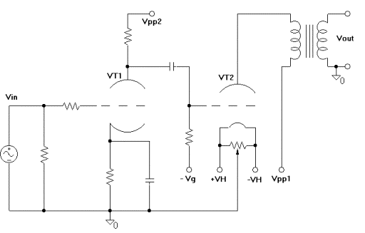
Fig.
4
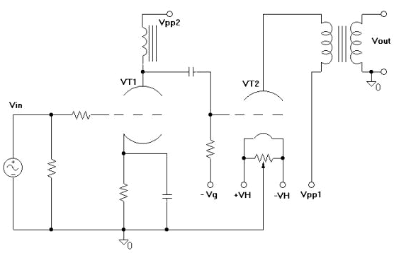
Fig.
5
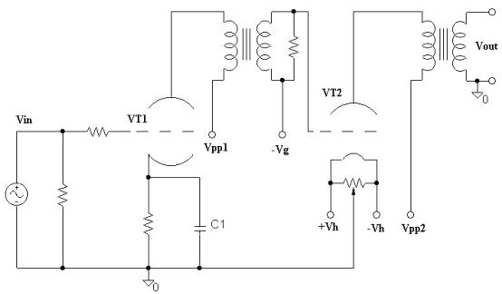
Fig.
6
From Fig.2, you have:
Ip1=g11*Vin1
+ g12*Vin1^2
(1);
Ip2=g21*Vin2 + g22*Vin2^2 (2);
Vin2=-Z1*Ip1
(3);
Vout=-Z2*Ip2
(4);
by
replacing the (1) and (2) in (3) and (4) rispectively it’s easy to reach at
the following expression for the output voltage:
Vout=
where:
Vin1=Vp*sinwt
(6)
and
therefore:
Vin1^2= 1/2*Vp^2*(1-cos2wt) (7)
Vin1^3= 1/4*Vp^3*(3*sinwt-sin3wt) (8)
(6)
is the mathematical expression of the input signal while (7) and (8) are derived
with a bit of trigonometry.
By
observing (5)
two main considerations emerge:
·
Also in the hypothesis of a 2nd order mutual dynamic
characteristic for the common cathode stages
the output signal present a 3rd
order component;
·
The algebraic expression between round brackets underlines the
theoretical possibility for an
annulment of the 2nd
order component and thanks to (7) also for the rectified component;
(g11,g12)=f(Z1)
(9)
(g21,g22)=f(Z2)
(10)
(where d1, the “error” produced by the first triode, includes distortions, noise, hum, drift and so on); next the criterion network b (that could also contain reactive element for frequency compensation) attenuates the amplified signal by the value
and
finally:
Vin1=
-G1*Vin
+ d1 (12)
Vout= -G2*{[(-G1Vin + d
1)*b]
+ d2}
(13)
G1= G2= G= 1/b; (14)
Vout= G * Vin -
d
1 + d2 (15)
and
d1 and
d2 are
similar if:
a)
both triodes are similar in their dynamic
behaviour;
b)
the
input signal swing it’s small;
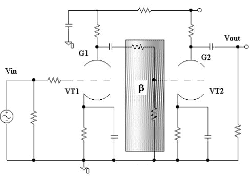
Fig.
7
therefore
a lower value in the output signal THD can
result.
The
reduction mechanism of even harmonics don’t have clearly the same
effectiveness that you can find
in ideal push-pull structures, where the input signals are really equal
altough out-of-phase. In cascade stages as in Fig. 7 the 2nd stage receive and
out-phase signal with the “harmonic
imprint” caused from the 1st one. I have defined
an Improvement Index (II):
 (16)
(16)
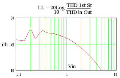
Fig. 8
The mechanism that characterizes the behaviour of the circuit in Fig.7 could be used, duly adapted, for the realization of an electronic phase inverter for push-pull amplifiers and for a line stage with low THD, Fig. 9. A similar preamplifier presents a cumulative gain as the first stage, a low THD and, thanks to cathode-follower, a low output impedance.
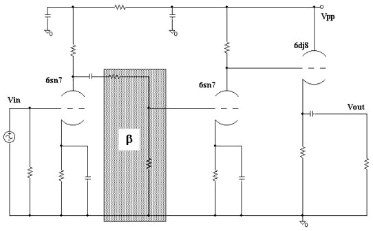
Fig. 9
Clearly, other circumstances
could require different bias points and/or vacuum tubes for the basic structure
in Figs. 7,9. For this situations an “ad
hoc” examen permits the best application of the HCT although the
procedural mechanism is the same.
References:
| 1 | Radiotron Designer's Handbook | RCA, pp. 509, 580-81, Chap XIV, 1953 |
| 2 | RCA Receiving Tube Manual | Technical Series RC-19, p. 344 1958 |
|
What did you
think of this article? |