|
|
>[]<
|
|
|
|
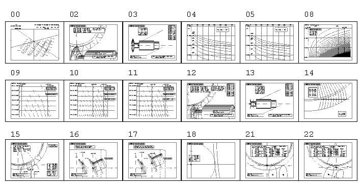
00U
|
* milling paths in continous mode (pinion)
|
|
|
01A
|
* Data sheet of example gear
|
|
|
02A
|
* Previous rough machining wiuth double-cone milling tool: layout
|
|
|
03U
|
* Previous rough machining wiuth double-cone milling tool: tool assembly
|
|
|
04U
|
* Error diagram in continous milling mode, for tool dia=250
due to path step and minimum curvature radius at root
|
|
|
05U
|
* Error diagram in continous milling mode, for tool dia=315
due to path step and minimum curvature radius at root
|
|
|
06A
|
* Optimized planning in multi-cut milling mode, from 2 to 8 cuts
by using 1 only milling tool; maximum over-stock is equal
|
|
|
07A
|
* Optimized planning in multi-cut milling mode, from 2 to 8 cuts
by using 2 milling tool spaced of normal basic pitch;
maximum over-stock is equal
|
|
|
08A
|
* Diagram for hand-calculation of cuts planning in multi-cut mode;
best results when external gap is balanced around external curvature radius
Calculated optimized planning belongs to this diagram
|
|
|
09A
|
* Diagram of otimized planning in multi-cut mode, with proper extra-radius
due to helix ; for use of 1 milling tool
|
|
|
10A
|
* Diagram of otimized planning in multi-cut mode, with proper extra-radius
due to helix ; for use of 2 milling tool , in case krc < 0,50 ;
planning is referred to path of front milling tool;
krc = tool distance / delta curvature radius
|
|
|
11A
|
* Diagram of otimized planning in multi-cut mode, with proper extra-radius
due to helix ; for use of 2 milling tool , in case krc > 0,50 ;
planning is referred to path of rear milling tool;
krc = tool distance / delta curvature radius
|
|
|
12A
|
* Machining layout in internal position = arrive point in continous
milling or innest cut in multi-cut mode
|
|
|
13U
|
* Tool assembly for involute machining, both continous and multi-cut mode
with minimum distance from table to gear edge
|
|
|
14A
|
* Rolling progression : linear increasing of both rotation and tool translation
|
|
|
15A
|
* Extreme positions in continous mode; Feed-fitting value K
and maximum axes speed
|
|
|
16A
|
* Side view of extreme positions, with movement of tool center over
a trasvere plane along X
|
|
|
17A
|
* Side view of extreme positions, with movement of tool center along
tool axe, on machining center or hobbing machine
|
|
|
18A
|
* Side view of milling tool in innest position, with eventual
extra-depth under tangent plane
|
|
|
19U
|
* Calculation of form error: table 1 : 1st value F1 due to path step
and tool diameter
|
|
|
20U
|
* Calculation of form error: table 2 : 2nd value F2 = form error
due to F1 and minimum curvature radius at root
|
|
|
21A
|
* Machining layout in continous mode with tool axe fixed (as by
an ordinary hobbing machine)
|
|
|
22A
|
* Machining layout in continous mode with tool axe oriented as normal
pressure angle : working area is always close to center
|
|
|
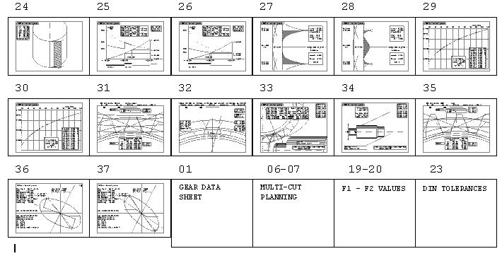
23A
|
* DIN allowance for example gear
|
|
|
24A
|
* Rolling area from Da to dNf
|
|
|
25A
|
* Feed-fitting diagram in continous mode + machining time, with 2 tools
for krc < 0,5 : first contact is by front milling tool
and following contact of rear tool makes X-Feed lower
|
|
|
26A
|
* Feed-fitting diagram in continous mode + machining time, with 2 tools
for krc < 0,5 : first contact is by rear milling tool
and whole Feed-fitting is referred to rear milling tool position
|
|
|
27A
|
* Continous milling mode: form error diagram along gear axe
in innest position, WITHOUT extra-depth of tool edge
|
|
|
28A
|
* Continous milling mode: form error diagram along gear axe
in innest position, WITH OPTIMIZED extra-depth of tool edge
|
|
|
29A
|
* Continous milling mode: form error when gear facewidth is
equally shared by machining paths, for tool dia=200 mm
|
|
|
30A
|
* Continous milling mode: form error when gear facewidth is
equally shared by machining paths, for tool dia=250 mm
|
|
|
31A
|
* Mating conditions of example gear pair, with local values
of sliding coefficient and fundamentals
|
|
|
32A
|
* Normal and trasverse profile, with tangent local axes for
tool thickness verify
|
|
|
33A
|
* Rough cut with thin milling tool : layout
|
|
|
34U
|
* Rough cut with thin milling tool : milling equipement
|
|
|
35A
|
* Mating conditions with reference rack
|
|
|
36A
|
* Ellipse diagram of matching gear-hob:
hob helix equal to gear helix L/L or R/R
|
|
|
37A
|
* Ellipse diagram of matching gear-hob:
hob helix reverse than gear helix L/R or R/L
|
|
|
>[]<
|
|

