THE WEIRD
BUBBLE ![]()
Here are some of the findings encountered during my experiments
![]()
Electromagnetic absorbing material
Current generation by friction
![]()
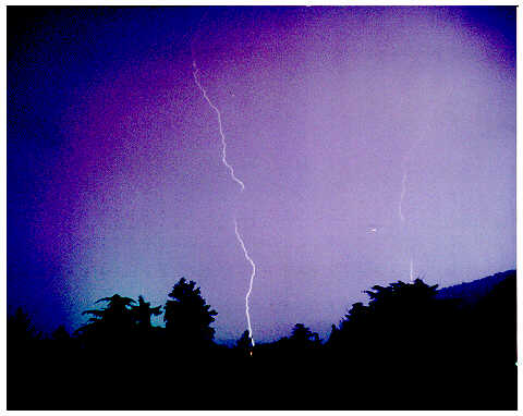 It is known that an intense magnetic or electric field is
capable of influencing the polarization of light (Faraday and Kerr
effect respectively). As I did not have access to neither of them I
thought that a lightning would be able to generate enough current, and
hence a strong magnetic field, which could polarize the emitted light.
It is known that an intense magnetic or electric field is
capable of influencing the polarization of light (Faraday and Kerr
effect respectively). As I did not have access to neither of them I
thought that a lightning would be able to generate enough current, and
hence a strong magnetic field, which could polarize the emitted light.
The picture was taken during a summer storm using a 35mm camera and a 35-85mm zoom set to about 40mm. The film had a 100ASA sensitivity and the stop setting was 4. A polar filter was placed in front of the lens and several shots were taken with the filter set at different angles. The shutter was kept open until one or more lightnings appeared in the field of view. Out of the total number of pictures only one clearly showed the effect of the polarization of light. This appears as a cancellation of the central portion of the lightning, probably it is the place where the magnetic field is more intense. A second lightning further on the right shows the same effect. Unfortunately I did not have the opportunity to replicate the experiment and this is the only proof available.
ELECTROMAGNETIC ABSORBING MATERIAL
If you try to
screen an oscillator coil with a metal screen you get an alteration of
the oscillating frequency and also a decrease of the amplitude due to
the damping factor introduced by the screen. An experimented solution
is to wrap the coil with semiconductive material. The material was
prepared using a sheet of paper covered with graphite from a soft
pencil. The type of pencil and the thickness of the deposited layer
gives the degree of conductivity. Incidentally this screen is also
effective against outside fields: i.e. an electromagnetic
field will not be able to detect the presence of a metal object if it
is screened by a semiconductive material. Another source of suitable
material is recording tape: ferric oxide or chromium oxide tapes work
well and the same applies to VHS videotapes. Wrapping the oscillator
with such a tape gives only a modest damping and the advantage is that
you can increase the 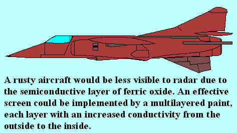 screening effect by wrapping more and more tape. I tried
also the thin conductor foil of a disassembled capacitor but
conductivity is too high: probably an even thinner layer of metal
would do the job. These experiments are several years old and I did
not experiment with the new metal tapes used in the "HiBand" standard.
screening effect by wrapping more and more tape. I tried
also the thin conductor foil of a disassembled capacitor but
conductivity is too high: probably an even thinner layer of metal
would do the job. These experiments are several years old and I did
not experiment with the new metal tapes used in the "HiBand" standard.
Maybe the Stealth aircraft is not detected by radar because it is "painted" with a semiconductive material and the microwave is absorbed and transformed into heat rather than reflected. The best solution would be in this case to have a multilayered paint: the layer in contact with the body of the aircraft would have a relatively higher conductivity while a second layer would have a lower conductivity.
A sound may appear to move
from one speaker to the other if the sound level is slowly decreased
in one speaker and, in the same time, slowly increased in the other.
With this principle in mind I designed a modulator that changes the
sound level fed to three speakers, in sequence. The process was
repeated for the other channel of a stereo system with a total of 6
speakers. Depending on the positioning of the speakers, you will be
able to get a sound depth and spatiality you never heard before and it
will make the most sophisticated surround system sound 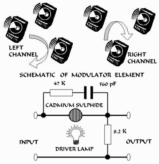 dull and flat. The period of rotation of the
sound should be adjustable between 1 and 10 seconds depending upon the
size of the listening room and the type of music being played. This is
accomplished with a circuit that generates a triangular signal driving
an incandescent bulb. A second triangular signal is triggered at the
peak of the first one, the peak of the second one will start a third
signal and the third will trigger again the first signal and so on.
Each circuit will drive its own bulb (12V 50mA) and one (two for a
stereo system) cadmium sulphide photocell placed right next to it. The
photocell will change its resistance, and hence the level fed to the
final amplifiers. Of course, you need also 6 power amplifiers, each
driven by the circuit shown in the picture. The input comes from the
preamplifier. The cadmium sulphide element is very slow but it is
quite adequate for this purpose. The bulb never switches off
completely in order to have a quick response from the cell and, in
order to avoid the "pumping" effect, the high frequency content of the
sound is bypassed and it is not modulated. The bulb is not fully on
either, this will lengthen the bulb life and will provide the right
resistance for the cutover frequency of the circuit. With this system
you will be able to recreate a true echo and the most incredible
effects can be reproduced by simply placing one of the speaker in
another room or mixing the left and right channel. After a while you
will no longer like the music in the traditional way although I found
that the voice sounds a bit unnatural if it wonders about in the room
so the system is not suitable to play vocalist pieces (except for
yodeling). The same bulb can drive one speaker of the left channel and
one speaker of the right channel. The original circuit used a total of
16 transistors and was built many years ago. I would think that a new
version might use DSP (Digital Signal Processing) thus obtaining a
higher quality and more versatility with the capacity to exclude one
of the channel or to change the depth, hence the effect, of the
modulation or to drive independently the left and right channel. The
system will not be cheap: not much for the cost of the power
amplifiers but for the cost of the speakers and it is suitable only
for large spaces: six speakers crammed together is not a nice view and
will not give the best effect.
dull and flat. The period of rotation of the
sound should be adjustable between 1 and 10 seconds depending upon the
size of the listening room and the type of music being played. This is
accomplished with a circuit that generates a triangular signal driving
an incandescent bulb. A second triangular signal is triggered at the
peak of the first one, the peak of the second one will start a third
signal and the third will trigger again the first signal and so on.
Each circuit will drive its own bulb (12V 50mA) and one (two for a
stereo system) cadmium sulphide photocell placed right next to it. The
photocell will change its resistance, and hence the level fed to the
final amplifiers. Of course, you need also 6 power amplifiers, each
driven by the circuit shown in the picture. The input comes from the
preamplifier. The cadmium sulphide element is very slow but it is
quite adequate for this purpose. The bulb never switches off
completely in order to have a quick response from the cell and, in
order to avoid the "pumping" effect, the high frequency content of the
sound is bypassed and it is not modulated. The bulb is not fully on
either, this will lengthen the bulb life and will provide the right
resistance for the cutover frequency of the circuit. With this system
you will be able to recreate a true echo and the most incredible
effects can be reproduced by simply placing one of the speaker in
another room or mixing the left and right channel. After a while you
will no longer like the music in the traditional way although I found
that the voice sounds a bit unnatural if it wonders about in the room
so the system is not suitable to play vocalist pieces (except for
yodeling). The same bulb can drive one speaker of the left channel and
one speaker of the right channel. The original circuit used a total of
16 transistors and was built many years ago. I would think that a new
version might use DSP (Digital Signal Processing) thus obtaining a
higher quality and more versatility with the capacity to exclude one
of the channel or to change the depth, hence the effect, of the
modulation or to drive independently the left and right channel. The
system will not be cheap: not much for the cost of the power
amplifiers but for the cost of the speakers and it is suitable only
for large spaces: six speakers crammed together is not a nice view and
will not give the best effect.
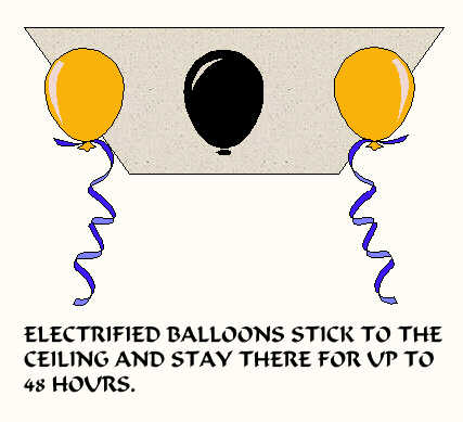 All
this started with the idea that negatively charged balloons would
float in the air and lift up on their own against the positively
charged air, a sort of electric buoyancy. Actually it did not work,
maybe because of the relatively low voltage available (-30KV) or maybe
because the idea was just not right. Instead I got the unexpected
result that the charged balloons would stick to the ceiling for a
remarkably long time, several days in certain circumstances.
All
this started with the idea that negatively charged balloons would
float in the air and lift up on their own against the positively
charged air, a sort of electric buoyancy. Actually it did not work,
maybe because of the relatively low voltage available (-30KV) or maybe
because the idea was just not right. Instead I got the unexpected
result that the charged balloons would stick to the ceiling for a
remarkably long time, several days in certain circumstances.
In order to charge a balloon you have to rub it against a cloth, curtain, tapestry, whatever, or bring it in touch with the screen of a switched on TV. Next, give it a gentle push until it reaches the ceiling where it should stop and not fall down. The critical part is to calibrate well the push imparted to the balloon, it has to "land" softly on the ceiling: if the push is too weak it will not manage to reach the surface and if it is too strong it will recoil and come down again. If you have difficulties with one balloon try another color: it appears that the pigment used changes the electrical properties of the balloon and this could be the reason why white balloons seem more difficult to place into "orbit". This effect can be used for didactic purposes or simply for entertainment: surprise is guaranteed.
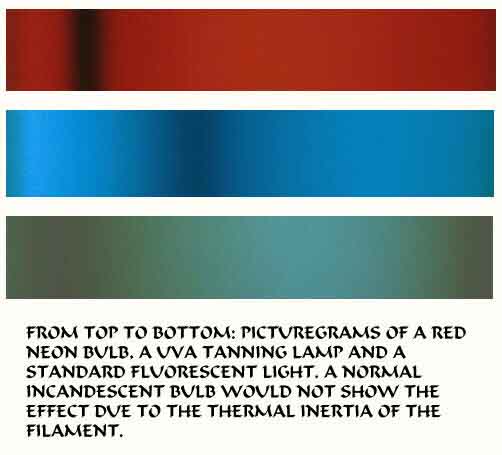 If
you set the camera shutter at 1/1000 or faster, you will be able to
record the moment when the light bulb goes off between on pulse of
light and the other. As it is known, light bulbs pulse with a
frequency twice the mains frequency: 120Hz in the States and 100Hz in
Europe. Our eye is not able to follow this fast pulsing but a properly
set camera may show exactly what happens to the light over one or two
pulses. The "picturegrams" on the left were obtained by setting the
camera at 1/1000 and then taking the pictures with the lens wide open,
actually if you remove the lens altogether you get a better result as
the picture must be totally out of focus. The camera shutters take a
certain time to travel across the film area and this time, in my case
it was 1/60 of a second corresponding to 16.7 msec, becomes the
"timebase" of the pictures. In this specific instance the laboratory
where I printed the negatives cut about 10% of the area so the actual
timebase of the picturegrams is reduced to 15 msec but enough to catch
the luminosity variation of the different bulb types. Use a sensitive
film: the one used in the experiment had a sensitivity of 1600 ASA and
you must get as near as possible to the light source, possibly at one
end or the other of the bulb. Cameras with a vertical shutter are less
suitable for this experiment and cameras with a lens shutter are
totally unsuitable for our purpose. The original aim of the experiment
was to assess if there was a color change in the light emitted at the
beginning or at the end of each pulse, specially in relation to
fluorescent lights, but it appears that such a color change does not
take place. Of course there is no use taking picturegrams of
electronic fluorescent lights: they pulse at a much higher frequency
and cameras are not fast enough for them.
If
you set the camera shutter at 1/1000 or faster, you will be able to
record the moment when the light bulb goes off between on pulse of
light and the other. As it is known, light bulbs pulse with a
frequency twice the mains frequency: 120Hz in the States and 100Hz in
Europe. Our eye is not able to follow this fast pulsing but a properly
set camera may show exactly what happens to the light over one or two
pulses. The "picturegrams" on the left were obtained by setting the
camera at 1/1000 and then taking the pictures with the lens wide open,
actually if you remove the lens altogether you get a better result as
the picture must be totally out of focus. The camera shutters take a
certain time to travel across the film area and this time, in my case
it was 1/60 of a second corresponding to 16.7 msec, becomes the
"timebase" of the pictures. In this specific instance the laboratory
where I printed the negatives cut about 10% of the area so the actual
timebase of the picturegrams is reduced to 15 msec but enough to catch
the luminosity variation of the different bulb types. Use a sensitive
film: the one used in the experiment had a sensitivity of 1600 ASA and
you must get as near as possible to the light source, possibly at one
end or the other of the bulb. Cameras with a vertical shutter are less
suitable for this experiment and cameras with a lens shutter are
totally unsuitable for our purpose. The original aim of the experiment
was to assess if there was a color change in the light emitted at the
beginning or at the end of each pulse, specially in relation to
fluorescent lights, but it appears that such a color change does not
take place. Of course there is no use taking picturegrams of
electronic fluorescent lights: they pulse at a much higher frequency
and cameras are not fast enough for them.
 Update:
I was told that actually there is a change of colors in the
traditional neon lights. Probably the shutter speed I used was too
slow hence I did some new experiments with a video camera with a
shutter speed set at 1/10000 of a second. There is indeed a color
change as you can see from the image on the side. The left part of the
picture is the neon normal color while on the right you can see the
color of the appliance that lasts for a very short time. A faithful
color reproduction was not possible: the original hue is more on the
orange side rather than a plain yellow.
Update:
I was told that actually there is a change of colors in the
traditional neon lights. Probably the shutter speed I used was too
slow hence I did some new experiments with a video camera with a
shutter speed set at 1/10000 of a second. There is indeed a color
change as you can see from the image on the side. The left part of the
picture is the neon normal color while on the right you can see the
color of the appliance that lasts for a very short time. A faithful
color reproduction was not possible: the original hue is more on the
orange side rather than a plain yellow.
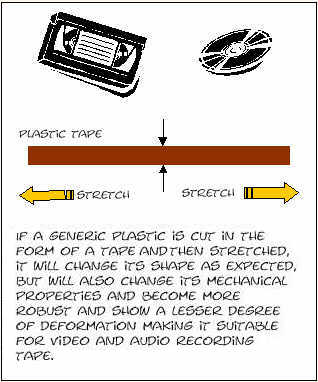 Any
plastic will deform easily when it is pulled or stretched. If you cut
thin strips of plastic 6mm wide and 100mm long out of any thin plastic
material, it will reach a length 3 times as long once it is stretched.
This operation can be done manually with a bit of practice. The width
of the stretched plastic will tend to decrease, two to 3 times the
original width and the thickness will normally decrease as well, but
not always: if the stretching operation is made with video tapes, you
will find that the actual thickness is almost double the original. The
substantial difference between the unstretched and stretched tape is
that the latter is mechanically more stable and it will not deform
easily and could become the ideal medium for audio and video tapes. I
was surprised to find the normal tapes, both video and audio, can be
easily stretched meaning that they did not go any pre-stretching
operation. Suitable plastics could be cut with predetermined width and
thickness, then stretched under controlled thermal conditions thus
obtaining a thin film with excellent mechanical properties. The
resulting tape will be thinner than current tapes meaning that you may
have longer reels with a higher recording quality due to the more
stable plastic support. Stretching speed and temperature are the two
important parameters that will influence the quality and dimension of
the end product and a good deal of experimentation must be carried out
with different types of plastic material although I expect that the
recording tape already in use is a good starting point.
Any
plastic will deform easily when it is pulled or stretched. If you cut
thin strips of plastic 6mm wide and 100mm long out of any thin plastic
material, it will reach a length 3 times as long once it is stretched.
This operation can be done manually with a bit of practice. The width
of the stretched plastic will tend to decrease, two to 3 times the
original width and the thickness will normally decrease as well, but
not always: if the stretching operation is made with video tapes, you
will find that the actual thickness is almost double the original. The
substantial difference between the unstretched and stretched tape is
that the latter is mechanically more stable and it will not deform
easily and could become the ideal medium for audio and video tapes. I
was surprised to find the normal tapes, both video and audio, can be
easily stretched meaning that they did not go any pre-stretching
operation. Suitable plastics could be cut with predetermined width and
thickness, then stretched under controlled thermal conditions thus
obtaining a thin film with excellent mechanical properties. The
resulting tape will be thinner than current tapes meaning that you may
have longer reels with a higher recording quality due to the more
stable plastic support. Stretching speed and temperature are the two
important parameters that will influence the quality and dimension of
the end product and a good deal of experimentation must be carried out
with different types of plastic material although I expect that the
recording tape already in use is a good starting point.
 remove s from address