Applications making use of toroidal rings
exploit the feature that the leaked magnetic flux is next to nil. This
allows, for instance, to design mains transformers with a very high
efficiency. The same applies to high frequency applications, provided
that the right material is chosen for the working frequency.
So it may sound nonsensical to use a plain toroidal ring
for the design of a stator for a synchronous motor as the magnetic
flux would remain totally within the core and would frustrate any
attempt to interact with an outside field which, in our design, would
be the rotor of the electric motor. Actually this feature of high
efficiency is employed in such a way to have a leaked magnetic flux of
high intensity by connecting, out of phase, the windings that were
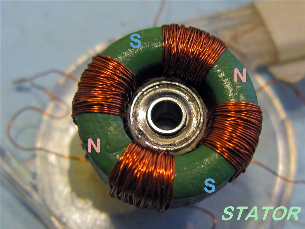
wound on the toroidal ring. As an experimental study a stator was
built with 4 identical coils, each of them made with 30 turns of
0.15mm diameter enameled wire.
It
would have been better to add more turns but to wind a wire on a small
toroidal ring is an extremely tedious job and at the thirtieth turn I decided I had enough of it.The ferrite ring you see in the
picture was recovered
from a discarded switching power supply. The ring outside diameter is
18.5mm. The material is far from ideal for a working
frequency of 50 or 60Hz. It would have been much better to have a ring
made with laminated iron, the same as the one you see in transformers,
but it is not an easy job to find one with the right size. I thought
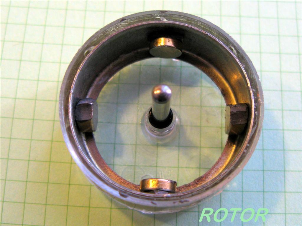
to make up for the rather low number of turns and the less than ideal
material for the ring by using, in the rotor, some small but powerful
neodymium magnets I had available.
For a single phase supply the number of windings must be
even, hence
they can be 2, 4, 6, etc. and must be connected in such a way that
like poles are always together, the south of one of the winding with
the south of the following winding and so. In this way the magnetic
flux will consistently leak out and interact with the rotor magnets
which must have the same number as the stator windings: 4 in this
case.
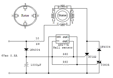
Synchronous
motors
do not start on their own with the exception of those with very low
inertia and power and some expedients must be devised to get them
running. In our case in order to have a mechanical design in its most
simple form, a circuit was implemented with the purpose to drive
separately both positive and negative half-waves depending on the relative position among
windings, magnets and sensor.
In practice, if all of them
are aligned on the same line the motor will always start in a predictable direction.
Moving
the sensor to the next
adjacent
winding will cause the motor to start in the opposing
direction. The sensor is placed outside the rotor so it can be easily moved to its designed
position and was recovered, together with other mechanical parts, from
a computer fan.
The circuit could be scaled to drive high
power motors and the one proposed should be seen merely as a
guideline. The motor rotates at 12.5 revolutions per second when it
has reached its steady state, i.e. synchronized with the mains
frequency, if this is 50Hz. A mechanical overload will cause the motor
to lose its synchronism but the electronic circuit will always try to
recover, within limits, the correct rotational speed. Actually its
speed could be changed by just changing the sensor position at some
intermediate place between two of the windings. The implementation of
such a design is rather straightforward compared to other kind of
electric motors and there is no drag and no resistance to its rotation
because the magnetic forces within the motor are always balanced and
in opposition thanks to the toroidal stator and the only drag comes
from the external load. Other motors with a toroidal stator that have
been proposed in the past had always some slots or protrusions thus
complicating its design and making them more costly as a consequence.
Another interesting
feature, common to synchronous motors and quite important if we go up
with power, is that the motor could be seen as a purely resistive load, 2.9 ohm in our case, thanks to the way
the coils have been connected. With small modifcations to the circuit
it is possible to get d.c. opertion as well.
The other measured
electrical
data are 1.2Vac across the motor once a steady state is attained and
0.41A flowing through it.
As expected, just like many electric
machines, it could operate as a generator. In this case other factors
come into play and keeping in mind that the set up is far from ideal,
0.4Vac were measured running at the same speed.
One peculiarity of this design is that the rotor is free to rotate
unhindered because the distance between the rotor magnets and the ring
is always the same and there is no preferred position where to stop.
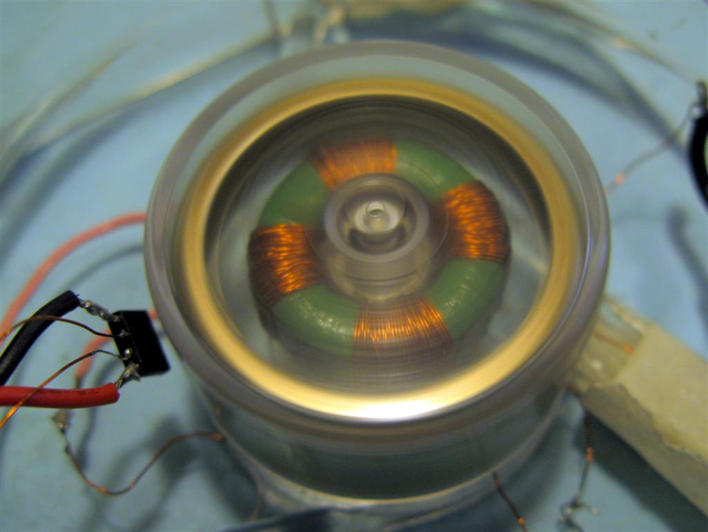
The last image shows
the assembled motor and fully rotating. The rotor is made of transparent
plastic thus allowing to see its inner stator. This comes handy when
placing the Hall sensor, the small integrated circuit on the left, at
the best place and to experiment the possibilities given by such a
construction.
The use of plain rings
to get a mechanical movement leads us to consider other applications as
well. Some of them could be quite new and it could be worth of
further investigation.
 Applications making use of toroidal rings
exploit the feature that the leaked magnetic flux is next to nil. This
allows, for instance, to design mains transformers with a very high
efficiency. The same applies to high frequency applications, provided
that the right material is chosen for the working frequency.
Applications making use of toroidal rings
exploit the feature that the leaked magnetic flux is next to nil. This
allows, for instance, to design mains transformers with a very high
efficiency. The same applies to high frequency applications, provided
that the right material is chosen for the working frequency.