Disclaimer:Every
damage you can cause after reading this page is not my fault! Be
careful of possible errors.
Bringing the Sony XA5400ES sacd player to a Hi-End level:
|
|
|---|
|
|
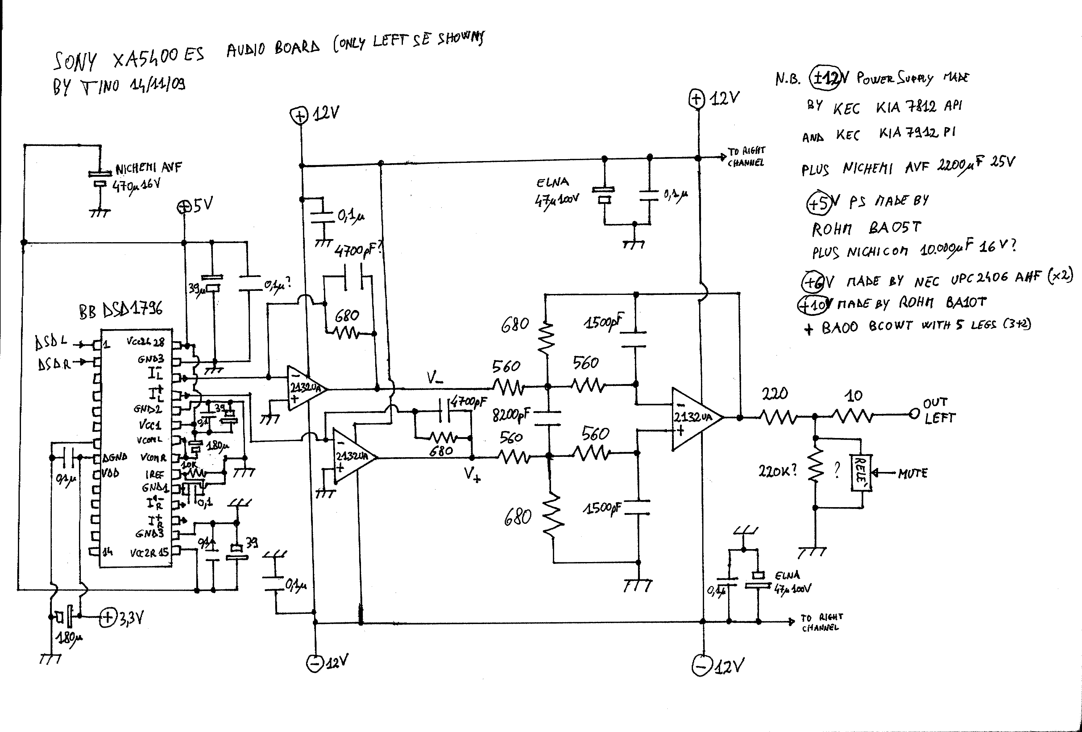
How much good can sound an OpAmp-based output stage, as the one shown in the scheme above?
How much difficult is to build a low feedback I/V conversion stage?
How much good can sound a “consumer” product like a Sony SACD player when tweaking its weak parts?
These and similar questions moved me to spend a lot of time and money to realize the project described here.
When, almost one year ago, I have bought my Sony XA5400ES player I was expecting a lot, since I have read wonderful thing about it from different sources (Stereophile, Audiogon, AVS, SACD-net,...). When I received it, initially I was really surprised by its high resolution, deep bass, good overall tone and so on... but after a long period of critical test I was convinced that it was not sounding in the “right” way. That is someway difficult to explain to one who don't really know how is the sound of truly hi-end gears and, in particular, of hi-end analogue sources. Let's explain it in this way: you can understand that its very detailed sound, despite its apparent no limits in the high frequency extension, is not properly “right” when you listen very carefully to human voices, violins, clavier, cymbals and other classical instruments, where the high frequency harmonics are essential to render the “complete true sound”, that you should know from your real-concert experience. If you listen only rock or electronic music, you will probably never complain with this -or many others- players!
Introduction:
First of all, I invested a lot of money to buy many well recorded SACDs. I already have tons of CD (including many audiophile MA Records, Harmonia Mundi, Astree, AliaVox, Alpha, E Lucevan le Stelle, Reference Recording, First Impression Music, Chesky, Opus3, and so on) but I decided to use as reference tests the best SACD records, because they contain much more details.
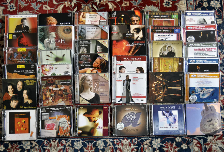
Among the many SACD that I have bought, here is a list of those which I have used more times as a reference:
the only SACD made by MA record, “MAonSA” (in particular tracks 4, 8 and 13). Note that track 2 of this wonderful SACD can't be read after the first 4' by the XA5400ES player. The MA Deux Ex Machina, Todd Garfinkle, told me that the same problem has been found on some top level Luxman and a few other players, that use some “new generation” Sony chip. On the Sony XA777 there is no problem to read the whole track 2 (almost 7') and the same happens on most SACD players;
one of the very few SACD from FIM: the sampler “Audiophile Reference IV” (in particular tracks 3, 10 and 16);
Channel CCSSA 16501 featuring the wonderful cello of Pieter Wisplewey and CCSSA 23606 featuring Rachel Podger violin with Gary Cooper fortepiano;
Pentatone PTC 5186095 and PTC 5186059 featuring the violin of Julia Fisher;
Mercury 470643-2 SACD reissue of the mythical “Firebird” by Antal Dorati;
Linn CKD 339 with the Phantasm cellos;
Fonè 016 sacd “Ludus Danielis”;
Verve 314589595-2 INO2 “Getz and Gilberto”;
Opus3 CD19623 Eric Bibb “Good stuff” and CD22014 “Lars Erstrand – The complete songs”.
Then, what one can do to improve the sound reproduced by this player?
I began studying how the XA5400ES was built and what the most known “modder” usually improve. Basically all of them (Allen Wright – Vacum State Electronics -, Dan Wright – Mod Wright -, Kyle Takenaga - Reference Audio Mods-, Alberto Ingoglia – Aurion -,...) replace the I/V and output buffer stage from a OpAmp-based to a discrete component-based. Some of them also improved or completely replace the power supply (PS) and probably only one (VSE) replaces also the clock circuit. All of them asked a price of 1000$ (or more) + shipping for these upgrade. I thought that it was too much (and was probably wrong) and decided to try the long path of DIY.
First of all, I looked for a “ready to install” circuit and asked help/suggestions on the http://www.DIYaudio.com forum. The thread title is “I/V + output discrete stages or transformer for DSD-1796”.
After this stage, I focused my attention on two very well regarded products:
Erno Borbely EB-108/435 or EB-109/437 ALL-JFET I/V converter, Filter and Buffer for DACs plus EB-208/418 or EB-703/259 regulator, e.g. http://www.borbelyaudio.com/pics/Web435DAC.pdf
Audial transimpedance + buffer stage LAB Module (by the good DIY member Pedja Rogic) http://diy.audialonline.com/modulelab/
The first had the advantage that can be configured also as a balanced to single end converter, so that I can build a SE output using both the information coming from the I+ and I- DAC outputs, while to do the same with the second I need to buy two LAB modules (for about 300 Euro) and two output transformers (about other additional 200 Euro for two top-level 1:1 Jensen). The Borbely kit was costing about the same total price (500 Euro), but needed more work to solder parts. From the experience that I have learned only after that, I can say that the Borbely price was not as high as it can firstly appear and that the Pedja Rogic LAB product is probably an exceptional value for the money. I didn't buy any of them simply because I didn't find a way to fit them inside the Sony case and I (read. “my wife”) didn't want to add an external additional box.
So it happened that I come to the true DIY land, that is, I had to build by myself something completely new. As a nephew I didn't have the competence to do it, but I was very lucky.
The first thing which helped me was that a German hi-end designer (let's call him “Mr C”) helped me to design a discrete I/V + buffer stage for the DSD-1796 DAC. I promised that I will not show anyone his design, so -please- don't ask me more details than those already written in this page. I will explain it in simple word and you will be free to develop your own version.
The art of I/V conversion:
While if in Internet there are described many I/V circuits, the majority (99%?) of CD/DVD/SACD player which use a DAC with current outputs use an OpAmp-based circuit? Not only it is easier and relatively cheap (OK, you can improve also the OpAmp to more performing types -as some good LT or AD-, but they will never become extremely expensive), but it is what the DAC designer had in mind when they designed the DAC chip. That is why, these kind of DAC (e.g. TDA1541-3, BB1704, BB1792-4-6-8,...) want to see a “virtual ground”, that is, an extremely low impedance load.
The other “purist” approach to avoid OpAmps is to do a passive I/V conversion, that is, to load the DAC output with a low resistance and then amplify a lot the voltage formed across that resistor. Of course, the DAC output will not see a virtual ground, but a relatively large load (or the voltage will be too low). Most of these DACs have some diode protections on their outputs. These diodes will start to conduce at a certain voltage, distorcing the musical signal. Let us suppose that 0.5V is the maximum permitted output voltage. If your DAC has ±2mA peak2peak of maximum output then you could use a 0.5/2mA = 250 Ohm resistor, isn't so? No!
In fact, most of these DACs have also a DC “bias” output current above which the signal current is modulated. Suppose that you have 3.5mA of DC bias current. Then you should use a maximum resistor of 0.5/(3.5+2)mA = 91 Ohm. Note that the signal voltage will be of only 90*(±2mA) = 0.36V peak2peak or 0.13V rms, so, in order to obtain the usual 2V rms you need to amplify that small signal 16 times (24dB).
Let's say that 100 Ohm is usually the maximum accepted value, but it is not strange to see I/V resistors (Riv) of only 50 Ohm, so that you can need even more gain. And of course you need immediately a coupling capacitor, in order to get rid of the continuous Riv*bias voltage.
Also the Borberly kits, which basically can be thought as a discrete (FET-based) super OpAmp, can be configured as a passive conversion followed by a high gain stage.
Another step has been taken by Audio Note (e.g. see the Adagio DAC by Thorsten Loesch), who developed a passive I/V stage based on two resistors with a matching transformer in between. I have not experience with that method, but my friend Faber has a TDA1541 (double crown) DAC similar to the Adagio and it sounds very well. Of course, the quality of the “I/V transformer” is mandatory.
Then it comes to the “active” but not-OpAmp circuits, where the not-OpAmp basically means that there are discrete transistors involved, but with no, or with low, global feedback. One of the most famous is the Jocko-Homo circuit, which you can find on the “easy to build I/V stage” thread and is similar to the “transistor” conversion described in the “DAC group” web page: http://members.chello.nl/~m.heijligers/DAChtml/Analogue/IV.html. Its basic idea is to use two transistors in a current mirror configuration. The first NPN transistor has its emitter connected to ground and then, because of the mirror principle, also the second transistor will have its emitter to 0V, that is, to a virtual ground.
The second idea is to fix the current on the second transistor (which is a common base) with constant current sources. If a current generator (the DAC output) will put some additional current on the emitter branch (I/V input) then you can connect a Riv resistor between its collector (I/V output) and ground and be sure that this additional current will flow out of the collector branch into the Riv resistor. In this way the input (emitter) does not see “directly” Riv (which is on the collector) and then can be much larger than in a passive circuit, eventually so large that you don't need any gain stage, but only a capacitor to get rid of the DC offset generated by the bias current. That is the base scheme of the circuit that I have built. I have used Riv=750 Ohm, giving 1.06V rms, in parallel with a 1 nF capacitor (giving a low pass frequency cutoff as high as 212kHz), followed by a unit gain FET buffer, similar to that published in figure 15C of Borberly 1999 “JFET: the new frontiers, part 2”, Audio Electronics 6/99, 16-20.
Another well known circuit has been published by the professor Malcolm Hawksford (a genius of audio electronics), and you can find it in his 2000 paper titled “Current-steering transimpedance amplifiers for high-resolution digital-to-analogues converters”, AES preprint. This circuit (figure 4.2) is much more complex, but has the advantage that Riv is not connected to ground, so that its signal could be free from dirty ground noise.
Another active circuit has been developed by Peufeu, while another one is called in Internet as the “Bakuun - satri DAC”. I have no experience with them. As you see, you can't anymore say that the only way to do a I/V conversion is to use an OpAmp. And remember what is said on DIYaudio: “Real men don't use OpAmp”!
The art of Power Supplying:
|
|
|---|
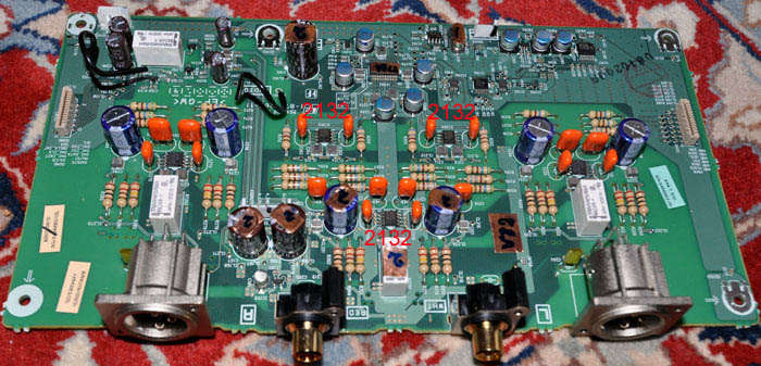
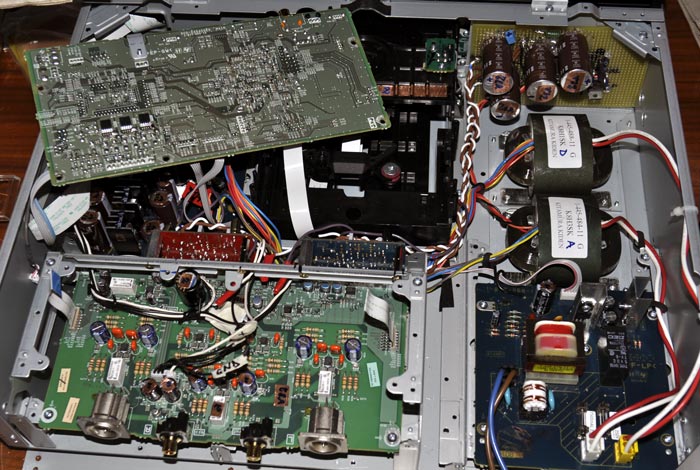
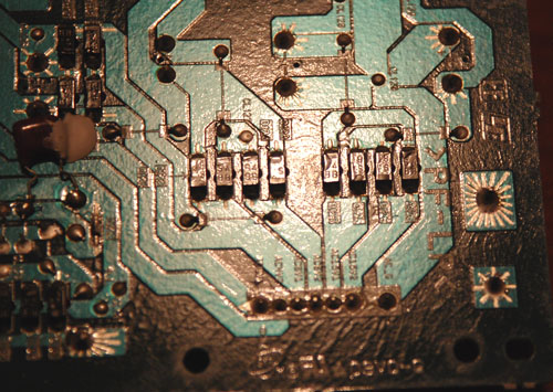
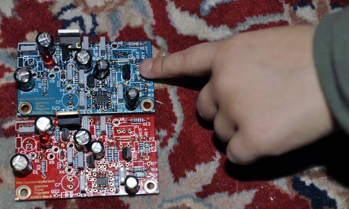
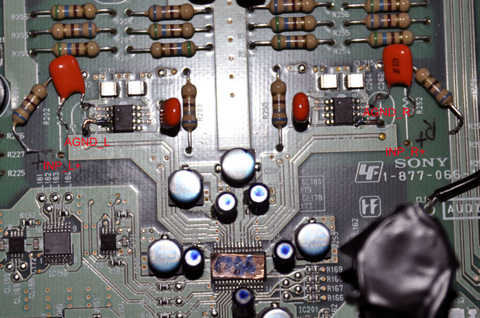
My basic idea was to build a new I/V and buffer output stage, but to retain the original power supply, maybe upgrading the capacitors. But then I saw how much I was spending in “esoteric” parts for the I/V and decided to look better to the original audio power supply. The main transformer is a nice Kitamura Kiden K8H3SK, able to provide a dual ±15V 150mA (but probably it will not die at 200mA). The regulated ±12V are made using a KIA 7812api and KIA 7912pi integrated regulators made by KEC, used after a 2200uF 35V ASV cap by Chemi-Com, and are followed by another 2200uF 25V AVF, always from Chemi-Com cap. Apparently not so bad, but then, what about the rectifiers? These were below the power supply board, being very small SMD diodes. I can't believe those tiny diodes are true hi-end stuff, nor I believe anymore in any miraculous 78xx ICs.
|
The original Sony power supply circuit for the analogue output stage and the DAC power supply (on the right). |
|
Then I started to study power supply regulators. I discovered that one of the most appreciated circuit was that designed by Walt Jung (another genius, who worked for Analogue Device), but it is not so easy to design. I understood that a good regulator should not only provide a constant voltage when its input varies, but should also offer the lowest output impedance to the load, and for a DAC it is mandatory that this output impedance remains low also at high frequencies, at least up to where the DAC output signal switches.
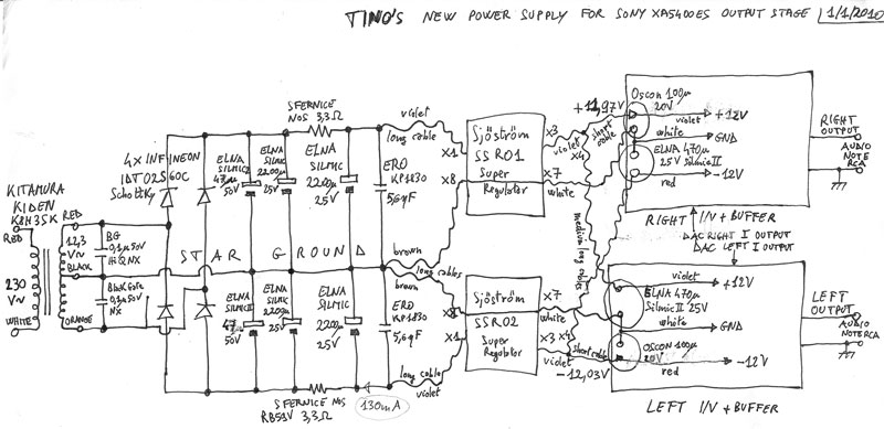
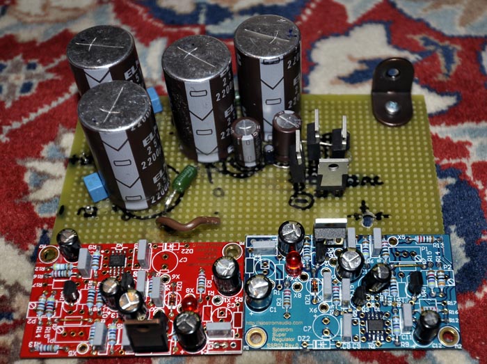
Then I was again very lucky, because professor Jean Didden (a well known expert of regulators) suggested me to use the design offered by Per-Anders Sjöström at http://sjostromaudio.com/joomla/index.php. After speaking with Per-Anders I bought his SSR01 (positive) and SSR02 (negative) super-regulators. He sells very nice -and small!- PCBs with soldered AD825 for about 50 Euro, but I asked him to sell me also all the needed parts to build a dual 12V PS, including the SMD AD825 OpAmp (used in a servo circuit) already soldered and the LM431 reference voltage IC. Since the Per-Anders super-regulators are from the Jung-Didden family, they are “series” regulators, but in my case the only component really in series is the fast D44H11 NPN power transistor, since I didn't installed the optional pre-regulator stage, based on the well known LM317 regulator. All other parts are used in the shunt regulation of the D44H11 transistor base.
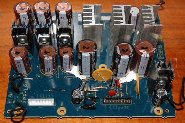
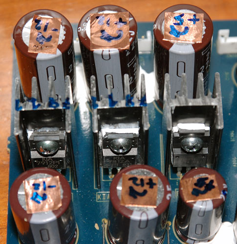
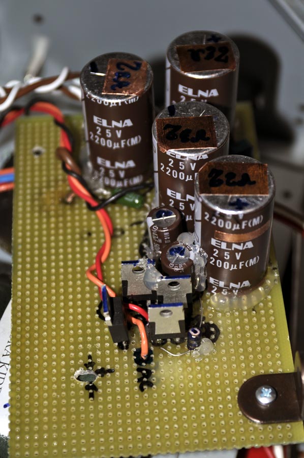
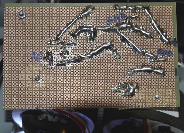
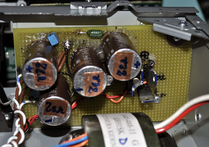
Of course, the SSR01/02 are only -super- regulators and hence does not include the rectification stage. So I had to design by myself a rectification board, which transforms the AC output of the Kitamura power transformer to -unregulated- DC. I designed it by myself and, of course, used the best parts I was able to find, since that was already becoming a cost-no-object project! I used my belowed Infineon IDT02S60C 2A Schottky rectifier, successfully used when tweaking my CJ preamp (as visible here). Then I have used two ELNA Silmic 2200uF 25V electrolitics, with in between a small 3.3 Ohm NOS resistor by Sfernice (just to check the absorbed current). The new power supply scheme is below.
|
|
|
|---|---|
|
|
|
|
|
|
Modify it!
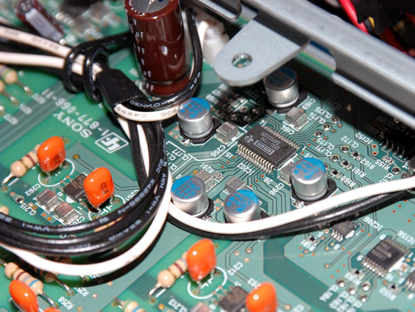
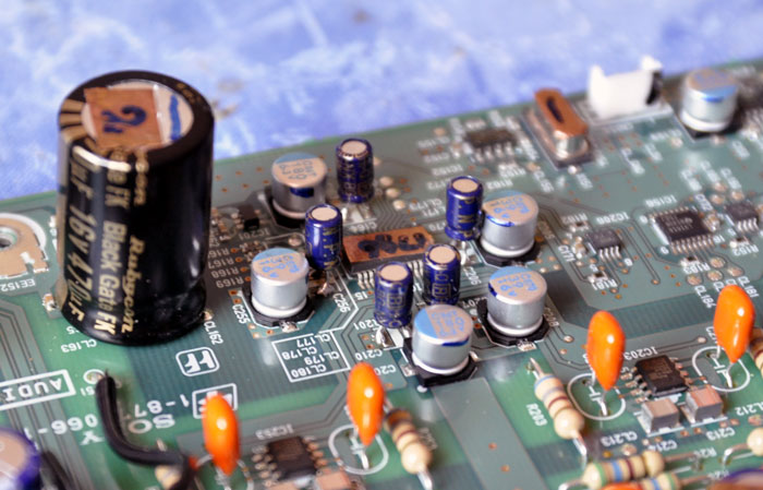
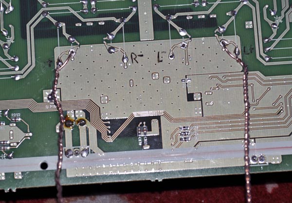
Since I was playing with the power supply, before to mount and install the Sjöström regulators I decided to upgrade the DAC power supply capacitors. Then I replaced the original 470uF 16V AVF Chemi-Con electrolytic with a massive Black-Gate FK 470uF 16V. This simple mod was immediately perceived as a “cleaner” sound.
Then I asked to a local lab to replace the SMD small ceramic caps used near the DSD-1796 DAC with Black Gate HiQ NX of the same value, that is 0.47uF for the two power supply decoupler (in parallel with 180uF electrolytic) and 0.1uF for the other three (in parallel with 39uF electrolytic). I was not sure if there was any difference in the sound, but I had the feeling of a less solid bass. If I would be able to manage SMS soldering I would come back from this mod, but since I have to pay -another time- to do it... I will leave them!
|
|
|
|---|
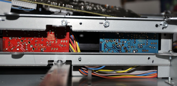
 After
this test I installed the two super regulators inside the Sony,
replacing the original ±12V
power supply with this “super-one”, but still using the
original OpAmp-based analogue board. The result was a revelation. It
was like to listen the Sony XA5400 on steroids! Everything
become much better: highs were much faster and less aggressive, bass
were deeper and better controlled. If you like the sound of this
player, I strongly suggest you to upgrade the analogue power supply
to SSR01/02 and to replace the 470uF cap with a better one. You will
really enjoy the result! Even more if you think that the total cost
will be about 90E for SSR01/02 + 65E for the rectifying board and
other 15E for the 470uF Black Gate. With less than 200 E you will get
a really big improvement!
After
this test I installed the two super regulators inside the Sony,
replacing the original ±12V
power supply with this “super-one”, but still using the
original OpAmp-based analogue board. The result was a revelation. It
was like to listen the Sony XA5400 on steroids! Everything
become much better: highs were much faster and less aggressive, bass
were deeper and better controlled. If you like the sound of this
player, I strongly suggest you to upgrade the analogue power supply
to SSR01/02 and to replace the 470uF cap with a better one. You will
really enjoy the result! Even more if you think that the total cost
will be about 90E for SSR01/02 + 65E for the rectifying board and
other 15E for the 470uF Black Gate. With less than 200 E you will get
a really big improvement!
Anyway, if you don't like the voice of this player, as I did, you will not be satisfied, because the “tonal voice” will not change. Even if everything seems to improve with these simple mods.
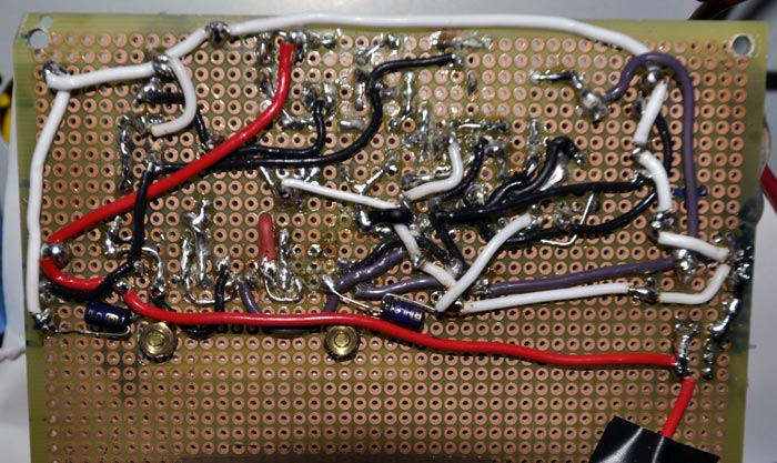
I have also brought the player after this mod to my friend Faber (who, BTW, provided all the teflon-insulated silver-plated wires that I have used), since some months ago he have used the original version for a while in his very revealing system. He told me that the player was less aggressive than was originally, while being even more defined and resolved in the high frequency, but yet the comparison with the Abbinghton Music Research CD77 was lost. When it comes to human voice... there is no competition and the AMR sound is much more “natural”. In his hi-res system, I have experienced also a little of listening fatigue, which was completely absent with the tube-based AMR.
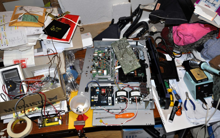
Going to heaven:
 Then
I had to build the new I/V circuit designed for me by Mr C and
describe above as a variant of the simple Jocko-Homo scheme. It was
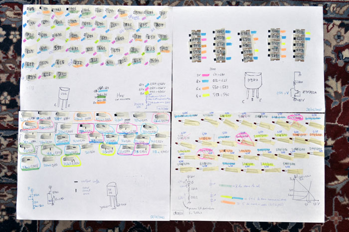
much longer than I thought. Matching siliceous devices (BJT, FET and
LEDs) was frustrating. The unavailability of a true lab was
detrimental for my family: I had to invade for months the “clothing
room” and my wife hated me! The path to audio-heaven is really
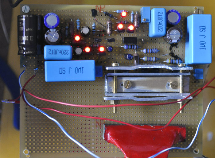
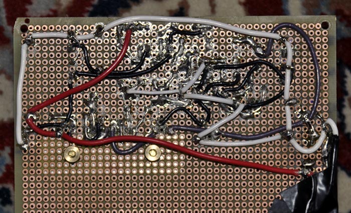
hard, but it deserve to be fulfilled! Of course I have bought only
the best parts: tantalum Shinkoh and Dale RN60 non-magnetic
resistors; OSCON, ELNA Silmic and Black Gate electrolytic; Rifa
PHE450 and ERO KP1830 polypropylene bypassing caps... not to mention
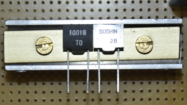
the Soshin SE99 silver mica 1nF in parallel with the 750 Ohm Shinkoh.
For sure I have spent more than 500 Euro only buying good parts!
Then
I had to build the new I/V circuit designed for me by Mr C and
describe above as a variant of the simple Jocko-Homo scheme. It was
much longer than I thought. Matching siliceous devices (BJT, FET and
LEDs) was frustrating. The unavailability of a true lab was
detrimental for my family: I had to invade for months the “clothing
room” and my wife hated me! The path to audio-heaven is really
hard, but it deserve to be fulfilled! Of course I have bought only
the best parts: tantalum Shinkoh and Dale RN60 non-magnetic
resistors; OSCON, ELNA Silmic and Black Gate electrolytic; Rifa
PHE450 and ERO KP1830 polypropylene bypassing caps... not to mention
the Soshin SE99 silver mica 1nF in parallel with the 750 Ohm Shinkoh.
For sure I have spent more than 500 Euro only buying good parts!
If the low pass capacitors was a no-brain choice, the coupling cap (high pass) was a tormented one. Since this cap couples the I/V with the high impedance FET unity buffer, its value can be relatively low, say in the 0.1-1uF range. When you came to coupling cap everyone has his preference. For example, if you look the following capacitor comparative tests you will note that everyone finds different results, even if Vcap TFTF and top Mundorf seems to be most preferred.
The Great Tempo Capacitor Shoot-Out;
Some Notes on Coupling Capacitors;
About Coupling & Power Supply Capacitors;
Eric Juaneda capacitors preference;
Coupling capacitor for 300B amp.
The “normal” choice would have been a MKP cap (e.g. Wima MKP10). The “esoteric” choice would have been a teflon cap (e.g. the new teflon-copper Vcap by VH), but I was wondering why I should pay a lot of money for a capacitor able to cope with 300 or more Volts when I need to decouple just 3V DC! At the end I chose to give more importance to take the path as short as possible and made the layout to accommodate a very compact non-polar Black Gate HiQ NX 0.47uF 50V. I can hear you shouting about my choice of an “electrolytic” (or better “electron transfer”) cap instead than a film one. I don't know, maybe one day I'll try a different one, but now it will be really difficult to fit anything else in such a small space.
|
|
|
|
|
|
|
|
|
|
|
|
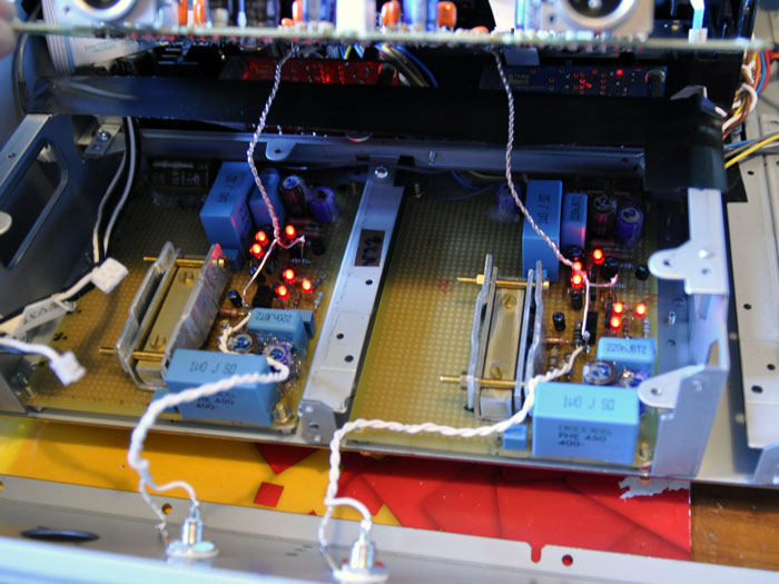
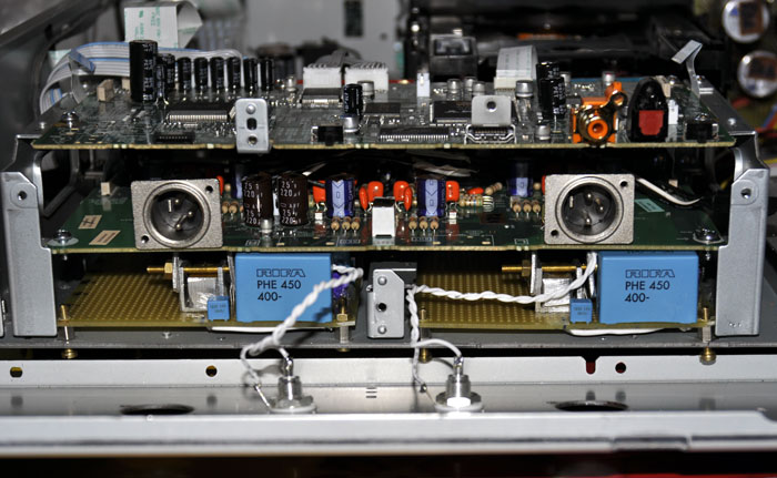
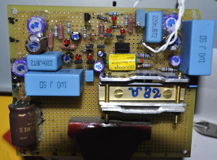
When I have built just two of the four new output stages I decide to listen the two I+ signals without waiting anymore. The Sony XA5400ES modded also in its output stage (let's call it “Tino Esoteric Audio” or “TEA” - Sony XA5400ES) impressed me first by how different it sounded from before. Anything was similar to what I have listened before from this player. Its voice was changed. Now it had a completely different voice... and personality. The only thing which resembled its previous life was its great resolution, but all the rest was different. That suggests that, given a modern DAC (note that the 1796 is quite cheap, much more than a BB-1704 was) with a good digital filter and a decent clock (with low jitter), then the I/V and the output stage of a CD/SACD player are dominating its final sound.
The second thing which surprised me was how much transparent the sound became. The mids became materically palpable. The highs became shining of true light and finally cymbals became as the real ones, with all the “natural” harmonic richness. The third thing which hit me was the tonal richness of its reproduction. It was as if before I was looking at images with 256 colours, while now I had a palette with 16 millions of colours. Now I can really appreciate the different tonal richness of violin from that of the viola, or that of bassoons from than of the oboe. Human voice became lastly... “credible”!
It is the perfect sound? Well, not. Unfortunately now the sound is lacking a little of dynamic punch in the low part of the spectrum. As Mr C. told me, it is not a yankee “WhamSlamThankYouMom!” circuit, but a orientally graceful one. So, if you live in Japan you will really love it, but if you live in US... I'm not so sure. I will try to work again in order to increase a little the dynamic impact and maybe will try different coupling caps (the high pass filter), but I can already live with this result. Also, I will try to finish the other two circuits (I- outputs) and will try to sum them with an output transformer (which I still don't know where I can put, probably above the Sony Audio board) to obtain a SE output built using the information coming both from I+ and I-. I hope also that the doubled voltage will provide more punch. As you can understand, this page is a work in progress.
Digression:
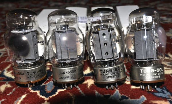
When I was fine tuning the new I/V+ output stage I went to a local electronic show. I visited the surplus tables, looking for good film & foil caps. Of course, I didn't find them. But, - unexpectedly – I found a quartet of old Tung-Sol 6550 (three of the “grey plate with 3 holes” type and one of the more rare “grey smooth plate” type) for a reasonable price. I bought them and found that they were not “as new”, but biased at higher potentiometer positions, as happens when a tube has already many hours of work.
|
|
|
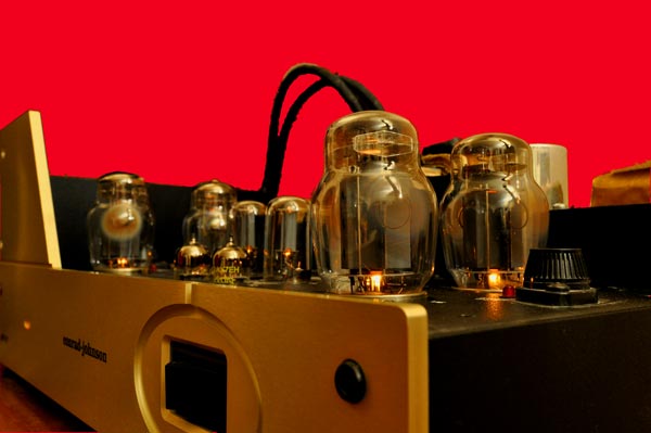
Anyway, when I replaced the standard Svetlana “winged C” (=C=) 6550 with these old tubes I was blown away by their transparency, meaning that even the smallest details were much better focused than before. Maybe they were lacking the strong bass of the Svetlana (remember that CJ voices his modern tube amps for the Svetlana 6550 tubes) but all the rest was much better than before and I had to re-calibrate my listening tests to this new -higher level- standard.
Modding the Mods:
After many listening test, in the hope to obtain a better “impact” on the bass response I decided to try what every friend told me to do, that is, I upgraded the small Black Gate NX 0.47uF used as coupling cap to a good film&foil one. I didn't chose the “best one”, but the “smallest one”.
|
|
|
 After
looking to many reasonable good cap I picked up the AuriCap 0.15uF
400V, which is 16mm long and has a diameter of about only 10mm. Even
so I had to put that cap above some resistors, because it was larger
than the space I had available.
After
looking to many reasonable good cap I picked up the AuriCap 0.15uF
400V, which is 16mm long and has a diameter of about only 10mm. Even
so I had to put that cap above some resistors, because it was larger
than the space I had available.
Sincerely I have not found a “big change” with this mod. Maybe the Black Gate was a little more bright and the Auricap more neutral, but the difference was not dramatic at all.
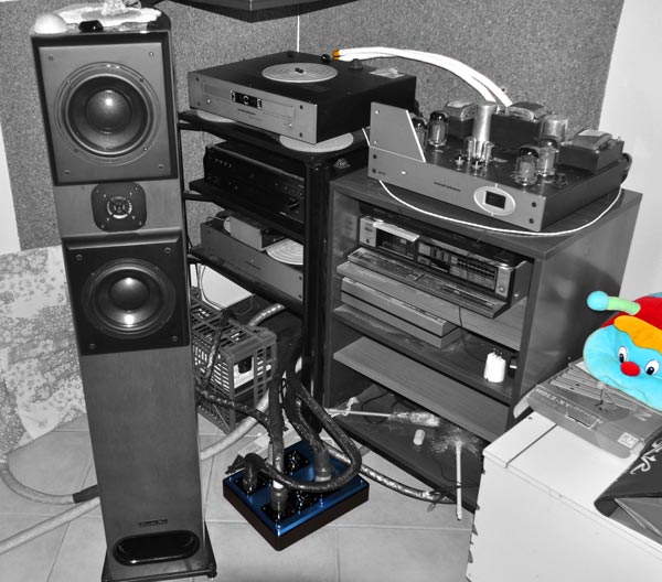
One day I received the visit of my friend Faber, who was interested in listening the last iteration of my modded XA5400ES and also want me to try his new products. After some hours of pleasant listening with my system we just replaced the signal cable going from the SACD player to the CJ preamp (which was a good Faber's Cable) with the prototype of his new top-level cable, that is, above the his “Xtreme Solutions” line. That change was really “dramatic”! The human voice become much more “physically” present and there were even more details than before. Lastly he want me to try his massive 6-socket plug, which is built from a solid block of aerospace aluminium and is more than 10 kg heavy. Also that was a very audible improvement, even if no so dramatic as the previous one.
Conclusions:
I came from the Hi-Fi world, where the famous names are Conrad-Johnson, Audio Research, Audio Note, Krell, Mark Levinson, Spectral and so on... and I landed in the DIY world, where famous names are Walt Jung, Malcolm Hawksford, Erno Borberly, John Curl, Nelson Pass, Jean Didden, not to forget Per-Anders Sjöström, Pedja Rogic (Audial), Jocko-Homo (alias Patrick Digiacomo, Audio Research Technology, TX), Mr C and many others whom I should thank for their sharing of true knowledge. Of course Mr C was the essential guy for this project and he deserve all my gratitude!
The sound of this TEA-mod player became extraordinarily clear, transparent, fast, rich of “tonal nuances”, with a sculptured soundstage (even if not so deep). How you can see this project is not yet finished (I would build other two circuit and use a transformer to convert the balanced signal into SE), but I urged to let you know how much better sound you can obtain replacing “what real men don't use” with discrete components.
Free Thoughts:
During this journey I had a feeling about some general considerations. Since they are “general” they are too simplistic to be always true, anyway I would like to share them with you. The first idea that I had is that -in general- an analogue front end sounds more “natural” than a digital player because it is more probable that the phono electronics avoid high-feedback circuits like the OpAmps used in most CD-players. The second though is that, generally speaking, tube-based electronics (in particular preamplifiers) sounds better than many of the solid-state counterpart not because tubes are inherently better than transistors (and FET in particular), but mainly because IC regulators are not frequently used with the high voltage needed by tube circuits and very often discrete regulation for B+ is used, which probably provide a better impedance at high frequency. Of course I can't prove any of these statements, but in future I will try to avoid electronics based on OpAmps powered by simple 78xx regulators!
NOTE:the second part of this work is described at this link!!!
Tino © March 2010