Inductive RIAA deemphasis Networks
A noticeable worldwide interest in the using of Inductive RIAA networks has always driven the tentatives for the improving the sound quality of phono preamplifers:Vinyl is back but many audiophiles think that its sound quality is still unsurpassed.
 |
 |
|
Excel Sheet |
|
Fig1 RIAA vs. IEC
The RIAA emphasis, a process necessary to reduce the amplitude of lower frequency and exaltate the higher ones for mechanical reasons (primary to efficiently write audio information on vinyl surface ), was historically obtained by a passive RLC network, Fig. 1, or by amplifiers with RIAA network on the feedback loop.
Fig.2 Passive RIAA Emphasis
Clearly the corresponding RIAA deemphasis can be obtained at the best (i.e. with the maximum accuracy) only by a similar dual network.
The Transfer Function in the s-domain of the RIAA deemphasis is:
|
|
eq. (1) |
where:
|
|
eq. (2) |
are the complex variable and time costants involved in the process respectively.
Fig.3 RC RIAA Deemphasis
In a theoretical way,
any transfer
function can be synthesized by an any complex RLC network (passive solution)
or by an active RC network (where this network is placed in the feedback loop of
an operational, or similar, amplifier). Further if the transfer function presents a gain (i.e.
a value greater then 1 in the transfer function for s ![]() 0 ) the synthesis problem is solved only by the active network. Fortunately RIIA
deemphasis transfer function do not presents a gain and the intrinsic
mathematical complexity of eq. (1) is very low.
0 ) the synthesis problem is solved only by the active network. Fortunately RIIA
deemphasis transfer function do not presents a gain and the intrinsic
mathematical complexity of eq. (1) is very low.
Fig. 4 Active RIAA Deemphasis
Audiophile community seems to refuse the active solution since the RC network is placed around a feedback loop ( no matter if the active device is a vacuum tube or a solid state amplifier) and for good reasons, since there is an historical, anecdotal and technical evidence that feedback amplifiers alter sound quality: for this reason the only acceptable way to build a good phono preamp is by the use of a passive stage (split or not around gain stages ). For economic reasons passive RIAA deemphasis networks are rarely in the form of a RLC quadripole (the only way to obtain the maximum accuracy) but appear in the lighter (and less accurate) aspect of a RC nertwork.
Fig.5 RLC Deemphasis Networks
A very simple topological transformation (in the s domain) demonstrates that electrical charecteristics of a RC network can be tranferred into a RL network derivated with the multiplication of the original network elements by the s variable. Starting from a RC network this transformation changes resistor into inductors and capacitors into resistors. Further and for practical reasons a scaling operation (multiplication or division by a costant) it's required to make values of the obtained elements (primarly the inductors) reasonable. Obviously we can realize also the inverse transformation from a RL network to a RC one.
Fig. 6 TANGO EQ-600P Specs
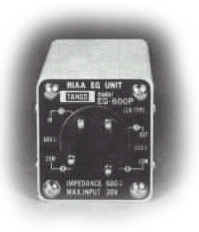
Fig. 7 The TANGO EQ-600P LCR Unit
Unfortunately a passive RL network used in the RIAA deemphasis presents a lot of problems. First we must introduce a DC block for the ground path: a large capacitors (in the region of tens microfarad) is often used: this reports the situation to a RLC network but without the accuracy that a perfectly (and ad hoc) conceived one can. Further the amplifier stages around a RL RIIA network must be direct coupled othervise other capacitors are necessary. Best way to solve this dilemma is to use a TLR (Transformer+LR) network. In this manner with the use of an additive element (the transformer) we can solve both problems. This solution is clearly expensive but probably is the best although, and again, we'll not have the accuracy of a specifically conceived LRC network. The mutual interactions between the output impedance of the active driving stage in union with the reactive/inductive elements of the transformer (parasitics and not) and values of the LR portion of RIAA network (parasitics and not) must be take in count with a deep analysis in order to avoid a further loss of accuracy. This solution is clearly device dependendant since a given tube or transistor require and ad-hoc designed transformer and subsequently a specified set of value for the LR portion.
Fig. 8 Japanese Phono with Inductive RIAA (from Radio Gijutsu, M. Yoshio Nasu, 1984)
PAEng can
design (under request) the best TLR network for a given device and for a given
phono preamp configuration. The accuracy of the released network can be greather
than ![]() 0.2dB. Evaluations, as usual, are made
by strongest recourse to Spice simulations and prototyping. TLR networks already
designed, are summarized in the Table 1.
0.2dB. Evaluations, as usual, are made
by strongest recourse to Spice simulations and prototyping. TLR networks already
designed, are summarized in the Table 1.
| Device | Air-Gapped TLR Network | UnGapped TLR Network |
| 6C45-PE | Yes | No |
| 6DJ8/ECC88/E88CC/E188CC | Yes | Yes |
| 5842/417A | Yes | No |
| 6H30 | Yes | Yes |
| CV5112/3A167M/437A | Yes | No |
| 12AT7 | No | Yes |
| 6SL7 | No | Yes |
| FETs | Under Request | No |
| Other Tubes | Under Request | Under Request |
Table 1. Designed TLR Network
An omnibus LR RIAA network
has been recently designed in order to remove the dependance of the chosen
active device and an unique coupling has eliminate the use of transformers.
Ther solution is cheap, very good sounding and the obtained RIAA accuracy can
reach the ![]() 0.1dBs.
0.1dBs.
Go to the corresponding Section.
References:
| Gobind Daryanani | Principles of Active Network Synthesis and Design | John Wiley&Sons, NY 1976 |
| Jean Hiraga | Etage phono à correction passive LCR | L'Audiophile, n°39, Automne 1986 |
|
What did you
think of this article? |