A PSpiced low-voltage phono preamplifier with harmonic distortion cancellation.
by Stefano Perugini
This
article appeared originally in Glass Audio
nr. 2/98
The decline of the VALVES-ERA, that corresponds to the higher cheapness
of solid state devices, was characterized by the achievement of vacuum tubes,
able to comply the increased demands to manipulate the electric signal, with
extraordinary features: Nuvistors, "computer grade" tubes, low-voltage
tubes, high-tranconductance low-resistance tubes, etc.
With all
respect for older and venerable valves, I believe that it is possible to obtain
remarkable results, from a point of view of the sonic, by linking to the use of
the above mentioned
typtology
of valves the modern tools for the PC-based circuits analysis (like
PSpice of the Microsim). All this make possible the "exploration" of
areas seemingly forbidden to thermionic technology and also, to carry out
objects that possess those sonic characteristics that have definitively decreed
the revival of the electron tubes in the Audio World.
With this article I'll show how with the 12+12 volts produced by two
batteries, a handful of components and 4 E188cc-SQ you can make a MM phono stage
with remarkable sonic characteristics.
Start
In
the world of the vacuum tubes it is inusual to meet with devices able to work at
a low power supply. Among the signal triodes it is natural to think about the
ECC86/6GM8; with its maximum plate voltage of only 30 volts, a transconductance
and an internal resistance of 3.6 mA/V and 7K respectively, it represents the
canonical choice when you want to elaborate the audio signal at low levels an
low power supply. A series of experiments convinced me that, however, the use of
valves, apparently not suitable for this aim, as the E88CC/6922 and E188CC/7308
(very similar tubes but not the same), can produce better results from the sonic
point of view even at a low power supply. Between the two, I have fully
preferred the E188CC/7308 because
in this appliance I have found a better alectric response and a more pleasant
sonic feature. But you must consider something else in addition: in the low
plate voltages area you cannot refer to the typical electrical parameters
carried on the data sheet; in fact both the transconductance gm and the m-factor
besides the fact that they are inferior to the typical values (in average more
than 50%), they present a stronger dependance on the plate and voltage current,
as a consequence, you need a greater designing effort if you want to control the
T.H.D. (total harmonic distortion) using "natural remedies". The way
is really tortuous but once you achieve your aim, the low power supply, enabling
you to an easy use of batteries, will repay you with a pureer sound, detailed
and rich of microinformations.
From the virtual.......
When you design a phono preamplifier, the targets on wich focus your mind
are two:
a)
the control of the distortion in the overloading condition;
b)
the synthesis of an accurate RIIA de-enphasis network.
To obtain the first result I've resort to the combined use of the local
negative feedback
and
the harmonic distortion cancellation technique. The latter, was often used at
the dawning of the "vacuum age" but soon left, after Harold Black had
his famous idea on the Lackawanna Ferry.
The harmonic distortion cancellation consists on the use of phase inversion characteristics, typical of a common-cathode gain-stage for example, in order to cancel, but actually only to reduce the harmonic distortion produced during the amplification process. You need, obviously, at least of two gain stage with complementary phase caracteristics.
To obtain the second result you must carefully model the single gain
stages (so you must know exatly the gain factors, the input and output impedance)
and tou must strategically set the three
main
time constants that caracterize the RIIA de-enphasis network.
In Fig.1 you can see the block diagram of the preamplifier (ro1, ro2, ro3 are the output impedance; A1, A2, A3 are the gains of the single stages; ri1, ri2, ri3 are the input impedance), while in Fig. 2 you can see the all circuit. The first two time constants are synthetized by the network between the first and the second stage, the third constant by the network included between the second and the third stage.
The Split RIIA method [1], apart from the fact that it permits a more accurate de-enphasis characteristic, in making the phase response between the stages more homogeneous, it helps the technique of the harmonic distortion cancellation in its job.
In Fig.3 you can see the frequency response of the phono stage and in Fig.4 is the frequency response with inverse RIIA. The charts have been obtained with an evaluation version of PSpice while the model of vacuum tubes is that of Mr. Koren [2] in wich, however, to the EX parameter a law of the polynomial variation with the plate voltage has been ascribed in order to render more realistic the behaviour of the virtual tubes and then the whole preamplifier in the low voltage and low current area. The coefficients of of the polynome have been obtained using the least squares method on the experimental data.
The prject of this preamplifier requires a lot of care in the containement of the distortion in overloading conditions fixed at +22dB with respect to the nominal value of 5.0 mVpp @ 1kHz of the input voltage, that is 3.55 Vpp. The aim is that of not overcome the 1% value of T.H.D. in overloading conditions because, over this value, phenomena linked with the intermodulation distortion could be audible. The examination of the Fig. 5 shows that with the technique of the harmonic reduction only, you can't reduce the T.H.D. for a wide range of frequencies, therefore a small quantity of local feedback is peremptory.
The harmonic reduction has been optimized around the frequencies close to 1kHz, where the human ear is more sensible. The final results of hours spent simulating the preamplifier are reported in Fig. 6.
Even thoug the output impedance is quite low (see Fig. 7), I don't
suggest to go under 50KW
as
load, otherwise you'll have an unaccetable rise of the T.H.D.
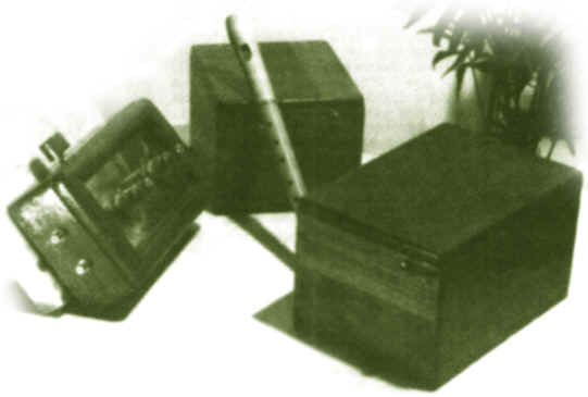
........to the real
Fig.
8
The physical realization of the preamplifier is shown in Fig. 8. The results of measurements on the real preamplifier have been in perfect accordance with the results of the simulations. That must not be a surprise because the parameters of the mathematical model used have been obtained in an experimental way from the tubes used in the preamplifier and not grom the average characteristics reported on the data sheet. If you set your project using the PC-based circuits analysis, I suggest to spend a little more time on the correct validation of the mathematical model. In Fig. 9 you can see the simple power supply, very effective both on an economic and sonic point of view.
In Fig. 10 I propose an hypothesis of battery charger. This circuit
produced with the chip L200, permits good re-charge of batteries. The maximum
charge current fixed by R4, R5 do not overcome 900 mA. R3 limits the reverse
current trought the regulator (wich should be 100mA max) when the battery is
accidentally reverse connected. If R3 is in series with a bulb of 12V/50mA
ratings this will indicate incorrect connection.
|
Part list for phono preamplifier Resistors R1 7k1501W 1% E96 Series R2 47K5W R3, R8, R14, R15 200W R4 169KW E96 Series R5 20KW E96 Series R6 8K06W E96 Series R7, R12 820KW R9 390KW R10 1KW R11 120 W E96 Series R13 604W E96 Series R16 220KW All resistors are 1/2W, 1% metal film, unless otherwise noted Capacitors C1 100pF Silvered Mica ACL C2, C4 100nF 50V MKS 02 Wima C3 4.7 x3 + 2.2 nF ACL C5 220 + 39 + 2.2 pF ACL Silvered Mica C6, C7 47mF Electrolitic Rubycon 50V C8 0.22mF 50V MKS 02 Wima Vacuum Tubes V1, V2 E188CC-SQ Philips
|
|
Parts List for the Power Supply |
||
| Bat1, Bat2 | NP7-12, 12V-7Ah | YUASA |
| Rld | 1kW | 0.5W, 5% |
| Dld | LED, 3mm RED | HP |
| Cpp | 47mF, 63V | Rubycon |
| SW1 | Bipolar Switch, 3A | |
|
Parts List for the Battery Charger (All resistors are 1/4W, 5% carbon film, unless otherwise noted)
|
||
| Resistors | ||
| R1 | 3.3kW | |
| R2 | 1kW | |
| R3 | 180W | |
| R4,R5 | 1.1kW | |
| R6 | 1.5kW | |
| POT | 1kW | Bourns |
| Capacitors | ||
| C1 | 470mF, 50V Electrolytic | Rubycon |
| C2, C4 | 100n, 50V MKS 02 | WIMA |
| C3 | 33mF, 25V Electrolytic | Rubycon |
| Solid State Devices | ||
| D1,, D2, D4-D7 | BY396P | General Instruments |
| D3 | LED, 3mm GREEN | HP |
| IC1 | L200 | ST |
References:
[1]
Morgan Jones,
VALVES AMPLIFIERS, Newnes 1995, pp. 268-287;
[2]
Norman Koren,
"IMPROVED VT MODELS FOR SPICE SIMULATION", Glass Audio, 5/96, p.18;
[3]
Charles Rydel,
"SIMULATION OF ELECTRON TUBES WITH SPICE", AES preprint 3887
(G-2), 98th AES Convention, Paris 1995;
[4]
Texas Instruments, ADVANCED BUS INTERFACE SPICE I/O MODELS, 1995 p. 1-10;
[5]
F. Langford-Smith, RADIOTRON
DESIGNER'S HANDBOOK, 4th Ed. 1953 pp. 535-537;
[6]
SGS-Thomson,
DATA on DISC CD-ROM.
|
APPENDIX PSpice
an the art of Harmonic Distortion Cancellation
The
advantage of the PC-based circuit analysis is that to underline the more
creative aspect of the design because it unable us to get free almost
totally from the tediousness of the numeric and symbolic calculation
that electronics drags everywhere. For example the right determination
of the phase response in a complex circuit takes only few minutes, on
the contrary, the same calculation done by hand and in a rough way could
take much more time. Complex procedures of measurement that
in the real world would require expensive instruments and long times of
preparation, can be made in a short and economical way. In
my project PSpice has been helpful to optimize the distortion
characteristics of the phono preamplifier.
I'll
report below the followed procedure to obtain a result like that because
I think that it can be used in other cases if properly adapted. a)
"Initialize" the preamplifier (that's to say, find the best
bias condition for the single amplification
stage) and synthetize the RIIA de-enphasis network; b)
With the PSpice statements .PARAM make variable the load resistance of
the first gain stage and through
the statements .FOUR and .STEP choose the value that produce the less
T.H.D. on the output node; c)
Repeat the same procedure, explained above, for the remaining common
cathode stage or else (as in the SRPP case) operate reducing the
superior cathodic resistance as to the inferior one on the respect of A1
Class.
|
|
What did you
think of this article? |