| Glass Audio Article nr. 6/98 |
A 24 Bit DAC
by Stefano Perugini
This
article appeared originally in Glass Audio
nr. 6/1998
The
Vacuum Tubes Renaissance appears more and more as an
intrinsic
characteristic of every sector audio; as well as in realizations
"tout-court"
you can see this fascinating and bright glassy bulbs in
increasing
symbiosis with the youngest products of the solid-state
technology.
The
presence of vacuum-tubes into solid state amplifiers (hybrid
amplifiers)
and in the output stage of the dac converters or in the musical
"processors"
of the pro-audio sector (where in
few cm2 of PCB you can
see
gathered DSP IC's and electron tubes) is
symptomatic, in my
opinion,
of the convicement that attributes to valves the ability to
compensate
the asperities produced by the solid state devices
and allow
therefore
the reproduction of a sound less straining for the human ear.
The
musicians for instance seem to have a preference for the presence of
vacuum-tubes
in power amplifiers
as well as in the analog signal
processing
and pre-amplification unities, while in the High-End sector
the
Audiophile Community reserve a
great attention to
dac's
with valves in output.
In
this article I'm going to introduce the project of a DAC converter
that
uses the recent Crystal's CS4390. This component that you can see as a
CS4329's
up-grade is a complete 24 bit stereo digital-to analog converter,
that
in addition to the traditional D/A
function, include a digital
interpolation
filter and a 128X oversampled delta-sigma modulator.
The
sigma modulation [1]
has now
come also to a technological
maturation
and can quietly rivalry both
sonically and technically with the
most
traditional multibit modality.
In
this project I have reserved great importance to the designing of
the
power supplies even featuring the eccentric use, for this context, of a
vacuum-diode
rectifer. The
output stage, thanks to the versatility of the
'90,
can lend to the most varied
designing interpretations. In this specific
case
you will see the implementation of a passive unity realized with a
signal
transformer.
Inside
the Blocks.
Fig.1
shows the
full block-diagram of the converter. The signal
coming
from the transport unity of CD-Player is submitted to an initial
conditioning,
that consists in an amplification and slope front
amelioration
, Block 2. The Block 2 output is the input of the Interface
Receiver,
Block 3. I have used here another Crystal's device, the
evergreen
CS8412. The CS8412 receive an decode audio and digital data
from
a digital audio transmission line according to the AES/EBU,
IEC958,
S/PDIF and EIAJ CP-340 standards. The (low jitters) clocks
generated are:
MCK
= 256 X Fs
SCK
= 64 X
Fs
Fsync
= Fs or 2 X Fs
where
Fs is the sampling frequency.
SDATA
the fourth produced signal, is correlated directly with the audio
information.This
data flow is input to the DAC,
Block 4, realized with
the CS4390. The 90's full Block-Diagram is shown in Fig. 2.
The
oversampling
factor permets the selection of an output filter based on out-
of-band
noise attenuation requirement rather than anti/image filtering [2].
The
delta-sigma modulator, Block 2, convert the interpolation filter
output
into 1 bit data @128X Fs. This data flow is input to the DAC
converter,
Block3, where the digital world bridge the analog world and
the
digital word translated into analog signal. Block 4 perform a low-pass
filtering
and allows two analog output with a phase difference of 180
degrees,
Fig 3. Each output produces 1 Vrms for a full scale digital
input.
In differential mode, where you can exalt the cancellation of
common
mode errors, noise, distortions and offsets, you can get up to 2
Vrms.
The
output Stage
The
noise spectrum in output from the 4390 presented in Fig.4, shows
clearly
the uselessness to apply a strong
low-pass filtering. In fact for this
operation
the same Crystal recommends the implementation of a 2nd
order
filter, however some experimental
tests show that good results can
already
be got with an a simple 1st order filter. Nevertheless the
4390's
good characteristics don't have to let think that the output filter is
superfluous
because some measures, that have found full confirmation in
listening
tests, have put clearly in evidence the presence of small levels of
distorsions
when the signal in output of the DAC is input to the
rest
of the audio-chain directly. In this project the filtering process has
been
realized resorting to the natural low-pass characteristic that a real
audio
transformer exhibits in the region of the high frequencies. This has
allowed
the realization of an output stage, Block 5 for the L-channel
and
Block 6 for the R-Channel in Fig. 1, with excellent sonic characteristics.
The output stage schematic is in Fig. 5.
Since
you can see this circuit as:
a)
a differential mode-to single ended mode converter;
b)
a low-pass filter;
it's
very simple to profit some correlated advantages with the architecture
of
the output stage internal to the
CS4390 .
Unfortunately
the simplicity of this stage is only apparent since a lot of
energies
can be dissipated for the search or the realization of a
transformer that answers to our specifics and for the circuit optimization;
the
load seen by the transformer is in
fact very complex because you
usually
have here a shielded cable that connects the output of the
conversion
unity with the input of the preamplifier. The knowledge of the
interactions
between the parasitic elements of the transformer,
the
connection
cable and the preamplifier input
circuit , it's of primary
importance
in order to establish the position and the entity of all the
resonances,
certainly out audio band, that would be able to move by
intermodulation
noise and distortion into the high region of the
audio
frequencies.
I
have conducted with profit this investigation entrusting me, as
usual,
to the circuit simulation [3]. The circuit used for the
simulation
is shown in Fig. 6. The components designated with an
asterisk
represent the parasitic elements of the real transformer.
More
precisely [4]:
Rti1*,
Rti2*, Rti3*, Rti4* are
the windings DC resistances;
L_leak_sc1*,
L_leak_pr1*, L_leak_sc2*, L_leak_pr2* are
the leakage
inductances;
C_lmpd_p*,
C_lmpd_s* are
the equivalent lumped capacitances between windings.
The
connection cable (the
Signal Cable black-box) has
been
schematized as transmission line [5], Fig 7.
I
have extracted the
large
sample of the High-End and Consumer production; by measurements
I
have extrapolated a real model of
worst
cable with
(Lp,
Cp, Rp) = (3uH, 300pF, 0.1ohm)
that
I have used for the simulations. Fig.8 is a Monte Carlo
analisys
related to the frequency response
of the circuit in Fig. 6 when R1
and
C_pre have 5% and 100% tolerance rispectively. Fig.9
show
a histogram evaluated with respect to Bandwidth("node", 1db) Goal
Function
[3], extrapolated from Fig.8. You can see that the
bandwidth
@1dB always falls between 21.6kHz and 23.5kHz, therefore
this
output stage well "defend" the correct frequency response from most
load
variations.
This
last results are not accidental or causal
since with a transformer of
smaller
quality the results won't be so good. From these simulations
a
peculiar behavior of the used transformer emerges:
the
low-pass characteristic that you
can observe in
Fig.8,
typical of every audio transformer, has been wanted
acting,
during the transformer building, on the values of
leakage inductances.
Simulations
have shown that this parameter has to lie between 10mH and
20mH.
Lower values of 10mH produce an excessive extension of the
bandwidth
worsening the DAC's noise levels. Greater values of 20mH
produce
a premature cut of the frequency response reducing the
informative
content of the audio high frequencies. Simulations and
measures
have shown an optimal behavior when the leakage inductance
assumes
a value of 16mH.
Alternative
roads
Naturally
a lot of equally valid variations to the scheme of Fig 5
exist.
If in this context you don't desire to renounce to vacuum tubes
you
could
take in consideration the simplified scheme of Fig. 10; as electron
tubes
I recommend the followings:
437A,
3A167M, EC8010, E810F in pseudotriode, 417A, E55L
in
pseudotriode.....
that
is small valves with high mu, high gm and a comforting plate
dissipation
in order to make easier the search or the construction of a
suitable
transformer, to get a better impedance matching and to produce,
in
case of necessity, also a meaningful output power . If you love to listen
to
music with headphone this can be
the road to follow for achieving
excellent
sonics results. Moreover since a
lot of Sound Card have a
S/PDIF
output, you can use this circuit to improve the sound reproduced
by the speakers of your Computer dramatically.

By
renuncing to the elegant
simplicity
of a transformer output stage (active
or passive), you can
entrust
yourself to the natural tendency of an op-amp to the differential-to
single_ended mode conversion.
In
Fig. 11 the scheme of a 2-pole
frequency
response. This filter has been designed with
a cross-frequency
of
50kHz, a 40dB/Dec slope and 6dB
gain. Obviously the circuit of Fig.
11
can be implemented with vacuum tubes technology getting good results
however, Fig. 13.
You
can find the grounds of this
circuit in GA 1/95
[7].
Nevertheless in comparison to the original version this schematic use only
6cg7's
and,
in order to simplify the realization I have chosen a SRPP as output stage.
Besides is
C10>C3
to
limit instability phenomenae in
sub-sonic band that this modifications can produce.
In
fact Fig.14 shows what happens in the frequency response
when,
with C3=4uF, C10 is varying between .2uF and 10uF with .2uF
step
. When C10 <C3 overshoots are
present in subsonic band. As
first
steps you can for instance choose C10=3.3uF and C3 = .22uF and
continue
with a following tuning on the real circuit. Unfortunately the
choice
of a low value for C3 introduces some disadvantage; Fig.15
shows
the simulated frequency response when Rl varies between
500ohms
and 20Kohms with step of 500ohms. A minimal value of
8Kohms
is necessary to avoid an excessive limitation of the low
frequencies.
In this context, since the realization of a vacuum-tubes op-
amp
is less critical than that of a
wide-band transformer , the influence of
the
parasitic elements can consider some more negligible and therefore the
electric
results more satisfactory.
Completion
The full schematic of the 24 bit DAC is show in Fig. 16.
The
dimensions
and consumptions
it features a good ability
to supply
current.
You don't have to worry about the elevated capacitive value of C35 and C36
since
the repetitive peak current, even in the most serious condition of
operation is lower of the maximum value, as Fig 17 show.
L1..L4
act in the decoupling of the high frequencies residuals; nevertheless their
small
values doesn't engrave heavily on the resonances of the power supplies filters,
Fig.
18.
The
shunt-type regulator for the voltage of the ' 90 have been chosen because it
effects
a
small degrade of the sonic
performances in comparison to the series
regulation;
then
whereas audio analog stage are present , the load is not onerous and,
as
in this case, it is not possible to
renounce to the power supply
regulation
, I prefere it to the serie-type regulator.
The
hands "in pasta"
I
have realized a first prototype of this converter with a point-to-
point
wiring, using small Teflon
clippings as support, Photo 1.
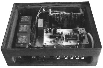
Photo1
Although
this solution is sonically effective , lately I have opted for
a
PCB realization in order to furnish in briefer times copies of this
converter
to the friends of the audiophile cenacle remained
fascinated by
his
intrinsic sonic characteristics, Photos
2, 3, 4, 5.
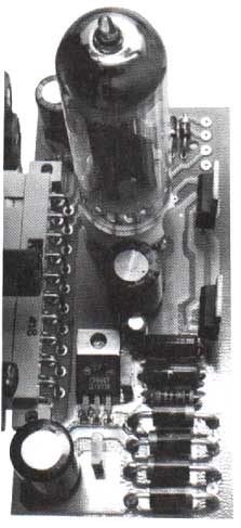
Photo2
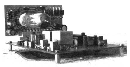
Photo3
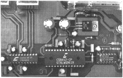
Photo4
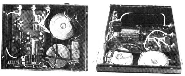
Photo5
Unfortunately
this approach determines an increase in the difficulties. In
fact
as every High-Resolution Mixed-Signal PCB Layout you will have to
respect
the followings constraints:
a)
Separate analog and digital circuits and segment by functionality and speed;
b)
Distribute power supplies and grounds taking care to minimize loop area and
return current paths;
c)
Isolate noisy return current paths from more sensitive analog circuits;
d)
Minimize interference from clocks;
e)
Decouple ALL IC power supply pin;
f)
Minimize emissions;
g)
Reducing the effects of capacitive and inductive couplings;
h)
Minimize return current path impedances to reduce ground bounce
effects.
For
instance with reference to c), the splitting of the ground into separate
analog
and digital grounds is the best way to guarantee that noisy digital
currents
will not flow in the sensitive analog area.
You
can see the adopted solutions in the Figgs. 19..22 that shows
the
PCB
artworks of the DAC.
Conclusions
The
ambitious objective to make the digital source timbre similar to
that
of an analogic source, or more simply to make harshless the resultant
sound,
is pursued generally acting entirely on the output stage side.
Most
of the high-end converters builders realize
this circuit using vacuum
tubes
and the results they get are good.
Nevertheless, also using an output
stage
with vacuum tubes, I think that a margin of improvement still exists
if
we also re-consider the constructive philosophy of the power supplies.
In
this light you can see the presence of a vacuum rectifier
and a shunt-
regulator
in the circuits of this converter.
Certainly
the presence of a vacuum rectifier into a low-voltage
power
supply can appear a bit " freak ", nevertheless I invite you to
experiment
a similar solution, not necessarily in this same context, since,
I
am sure, the results will impress you positively.
This
project was conceived initially two years ago thinking at the
CS4329
(the predecessor of 4390, with the same pin-out). During the
time
continuous improvements have been effected in order to get both
a
minimalist and well sounding object . A possible evolution of
this
object could foresee power supplies with
choke input filter and
vacuum-tubes
shunt regulators.
References:
[1]
T. Tanaka, T. Sugimoto, C. Kubomura
18-bit
D/A converter with integrated digital and analog filters
91st
AES convention, October 1991, New York, Pre-Print
#3113(y-1);
[2]
Crystal Semiconductor Corp.
24-Bit,
Stereo D/A converter for Digital Audio
DS264PP1,
May '97;
[3]
Microsim Corp.
Microsim
DesignLab Eval. 8, 1997;
[4]
Radiotron Designer's Handbook, Fourth Ed.
pags.
204-206;
[5]
Douglas Self
Cable
Sonics?
Electronics
World, Vol. 103 No. 1738, October 1997;
[6]
Crystal Semiconductor Corp.,
Evaluation
Board for the CS4329
DS153DB2,
Aug. '95;
[7]
Fred Forsell
A
Vacuum Tube Op Amp
Glass
Audio, Vol. 7 No. 1, 1995;
[8]
Norman Koren
Improved
Vacuum-Tube Models for PSpice Simulations
Glass
Audio, Vol. 8 No. 5, 1996;
|
What did you
think of this article? |