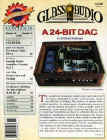
A 24 Bit Audio Dac

Full Article Here


Fig. 1 The BLock Diagram

    The full article about this Digital to Analog Audio converter was presented on the issue nr. 6/98 of Glass Audio Magazine. This project features a CS8412 as Interface Receiver, a CS4390 (24 bit Delta-Sigma DAC) as Audio DAC and a custom audio transformer (with m-metal core) as output stage with inherent low-pass filter and differential to single-ended converter. The simplicity of the output stage permits (outstanding) sonic results much better than a vacuum-tubes circuit.

I have reserved a great attention to power supply. A combination of vacuum diode rectifier, shunt-type regulator and inductive p-filter was mixed.

Fig. 2 MonteCarlo Results

The parasitics of output transformer contributes both to out-to-band noise attenuation and anti-aliasing filtering.Tolerances don't affect audio band (see the above MonteCarlo results obtained with Microsim DesignLab/PSpice Eval. Ver. 8.0)

Fig. 3 The Full Schematic (click on image to enlarge)

Fig. 4 The Full PCB (click on image to enlarge)


                                   Tab. 1
Part List for DAC Converter
(All resistors are 1/4 Watt, 1%, metal film)

a) Resistors

R1                              75ohm

R2, R26, R27            100ohm

R3, R22, R23            10Kohm

R4                             47Kohm

R5                             100Kohm

R6                             1Kohm

R18, R19, R20, R21 16Kohm

R24, R25 8.2Kohm

b) Capacitors

C1, C6                            10nF 63V X7R SR21 Series  AVX

  C2, C5, C7, C11,..
  C13, C15, C17, C18    100nF 63V   MKT  
    
C3, C4, C8, C10,..
C12, C14, C16, C19     1microF 63V        Panasonic

C9                                 47nF 63V X7R SR21  Series  AVX

C40, C41, C42, C43     100pF 63V X7R SR15 Series  AVX

C44, C45                      1microF 63V        MKT

c) IC's

IC4 CS8412        Crystal Semiconductor

IC5 CS4390        Crystal Semiconductor

IC6 74HCU04     SGS-THOMSON

d) Transformers

TR1, TR2 Audio Transformer   Custom

e) Miscellaneous

JCK1, JCK2 RCA                 Female Jack

JCK3 RCA                            Female Jack for S/PDIF

SW2 316-973                        RS-Components

                              Tab. 2

Part List for Power Supplies
(All resistors are 1/4 Watt 1% metal film unless otherwise noted)

a) Resistors

R7, R11         10ohm

R8, R9           10Kohm

R10, R13       220ohm

R12                750ohm    0.5Watt

R14,R15        0.68ohm   5% 2.5Watt  W21 Series   Welwyn

R16               10ohm    0.5Watt

R17               330ohm 5%   9Watt  W23 Series   Welwyn

b) Inductors

L1..L4 240-551                         RS-Components

c) Capacitors

C20, C30, C33, C34,
C47                                   1microF 63V         Panasonic

C21, C22, C25, C27,..
C29, C31, C39, C46         100nF   63V         MKT

C23, C24, C26, C28         100microF  25V         Rubycon

C32                                   2200microF  25V Rubycon

C35, C36                          220microF  63V Rubycon

C37, C38                         330microF  25V Rubycon

C48, C49                         100pF  2kV Disc        Panasonic

C50                                 33nF  250Vac Y2 MKP   Philips

d) Diodes

Solid State:

D1, D2, D7..D10 1n4007

D3..D6              1n5401

Vacuum:

VT1 EZ81 Sylvania

e) Transistors

Q1, Q2 BDW94C SGS-Thomson

Q3        BDW54C SGS-Thomson

f) IC's

IC1 MC7806 Motorola

IC2 LM317T Motorola

IC3 TL431C Texas Instruments

g) Power Transformers

TR3
Pri: 220Vac
Sec: 2 X (0-55), 0.45A Nuvotem-Talema

TR4 Pri: 220Vac
Sec: 2 X (0-9), 1.7A Nuvotem-Talema

h) Miscellaneous

SW1 320-938                       RS-Components

FLT210-409                         RS-Components

TRNSZ1.5KE 300CA          General-Instruments

LMP194-694                        RS-Components

Fuse1, Fuse2 315mA Fuse    T-Series


Fig. 5 PAEng SOT Pinout

Photos Gallery

Photo1 Details of the mixed signals core (click on image to enlarge)


Photo 2 The full Audio DAC (click on image to enlarge)


Photo 3 An assembled prototype (click on image to enlarge)


Photo 4 PCB Details (click on image to enlarge)


Photo 5 The DAC inside a Marantz CD Unit (click on image to enlarge)


CD Transport Unit MKI (Philips)  + DAC Board


Photo 6 The Transport Unit MKI (click on image to enlarge)


Photo 7 The DAC Board