![]()


![]()
![]()
![]()
The HYBRID Printed Circuit Board
Balanced Inputs for the HYBRID (New)

It is a simple design that incorporates interesting ideas such as the Zen project of Nelson Pass, tubes low voltage operation (Erno Borbely, Glass Audio vol.10, num.1, 1998) and the Zen output stage with differential power supply (Reinhard Hoffmann, Audio Electronics num.4, 1998).
The HYBRID amplifier is a two-stage, DC coupled, single-ended, Class-A amp, capable to deliver around 30W in an 8ohms load or 15W in a 4ohms load. The output power can be easily increased by paralleling more output Mosfet devices and its associated current source. Parallel devices will contribute to increase the damping factor and lower the dependence from the load impedance. A stereo amplifier with two outputs Mosfet devices per channel will provide more than 50+50W of pure Class-A usable power to 6-8 ohms loads. Due to its Class-A operation, in such conditions the stereo amplifier will dissipate more than 300W, therefore appropriate heat sinks (at least with a thermal resistance of 0.2°C/W) and a suitable well-ventilated enclosure must be used.
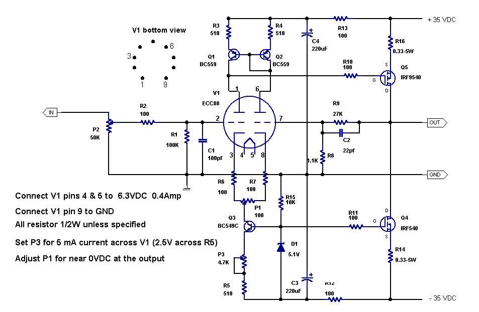
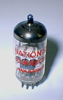
The input stage is based on the 6DJ8 a double triode tube (also know as 6922, ECC88, or E88CC) in a differential amplifier configuration. I selected the 6DJ8 tube for its linearity and its good operation at 35-40 volt anode voltage. For the 6DJ8 the mu factor is constant within 20% from 0.4mA to at least 6mA, and the trend continues to flatten to 15mA. I choose an operating current of 3-5mA for each half of the stage and a plate voltage of 35-40V, respectively, to keep the dissipation well below the rated value of 1.8W. You can achieve almost all of 6DJ8's virtues at 5mA or lower.
The cathode current is supplied by a constant current source composed by Q3, while Q1 and Q2 forms an active load or current mirror. The active load forces the anode/cathode of both triode currents very close to equality, giving excellent cancellation of the second-harmonic distortion, and contributes to linearize the operation and increase the common-mode rejection and slew rate.
With P3 is possible to adjust the bias current from 1 to 7mA approximately, and P1 controls the output offset voltage that must be adjusted near to 0V.
The output stage is composed by one or more P-channel Mosfet in a single-ended, Class-A, common-source configuration, similar to the Nelson Pass Zen amp (for more details see http://www.passlabs.com/zenamp.htm).
Its drain current is supplied by a constant current source composed by Q4, which is generating a 3A idle current. The amount of idle current (Id) depends on the value of R14 and different values can be experimented using the following formula:
[ Id = (Vz-Vgs) / R14 = 0.9 / R14 ] where,
Vz = zener voltage
Vgs = Gate-Source threshold voltage (typically ~4-5 volt)
When defining different idle currents, the maximum ratings of the Mosfet output devices must be considered. In general, the Class-A stage must carry a current of at least 50% more than the load will draw.
The overall closed loop gain of the amplifier is around 20 and its depends on the values of R8 and R9. In such a way a 1V input signal will drive the amp full power. So, the output level of a typical CD player is sufficient to drive the HYBRID amp. A different gain may be calculated using the following formula:
[ Av = 1+(R9/R8) ]
Hybrid amplifier Set Up
For the Hybrid amplifier set-up only P1 and P3 must be adjusted.
Start with all trimpots at middle position. Adjust P1 for a zero offset voltage at the output points, and set P3 for a 5mA current over V1 (2.5V across R5).
The HYBRID circuit schematics
NEW
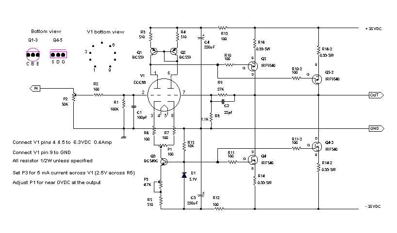
The HYBRID+ circuit schematics.
An enhanced version of the Hybrid for up to 100W of output power.
A typical ECC88 tube
 itle
A
itle
A
| Specification and max ratings | ||||||||||||||||||||||||
|