
Frame Rate Prediction[2007.04.26] |
|
|
Trying to find the correct budget for robots and sensors lead me to search some rational solution to this apparently unsolvable problem. The budget is a tough problem because it depends on many parameters and we are not able to tell some good numbers valid in all situations.
That's why I thought to write down a budget equation that can handle any case. With this equation we can reasonably predict if the chosen robots and sensors configuration will run with an acceptable frame rate (on the same machine we used to measure the parameters of the formula).
As I told before, the budget depends on many parameters. I choose only that ones that we can easily measure and that can implicitly embed also other variables (like the point of view, map type etc.):
| : (ascii: tL) time required to make a laser scan in ms. | ||
| : (ascii: fL) number of scans per second for the laser scanner | ||
| : (ascii: nL) number of equipped laser scanners | ||
| : (ascii: tV) time required to make a victim sensor scan in ms (I mean each scan, not the 4 scans used to output the results) | ||
| : (ascii: fV) number of scans per second for the victim sensor (as before, we count each scan) | ||
| : (ascii: nV) number of equipped victim sensors | ||
| : (ascii: tf) time required to render a single frame without any robot in the map, in ms | ||
| : (ascii: tiR) processing time required by robot of type i, in ms | ||
| : (ascii: niR) number of robots of type i |
As you can see, I omitted other sensors like odometry, inertial unit etc. because their computational time is negligible.
I assumed, for sake of simplicity, that all these parameters are constant. This is not true, most of the t parameters depend also on the number of robots. So we have to take some average value. We can measure the frame time with several robots (all the same kind) in the map, also changing the view point, and find the average time required to compute that kind of robot. We can repeat this measurement for all kind of robots we are interested to use and find this way all tiR parameters. To find tL and tV I coded a very simple robot, called STLR (it's a Zerg), that uses Clock() and UnClock() unreal script functions to measure the processing time for every mounted sensor. To find tL make sure that you set ScanInterval in [USARBot.RangeScanner] to some big value because STLR activates the scan manually.
Now that we hopefully have all the parameters, we can predict, with some approximation, the frame rate of the simulator with the following equation:
Let's see how this equation woks. If we have no laser scanners nor victim sensors, then the frame rate is simply:
If we visualize the denominator with a green block, we can graph the frame rate like this:
Now, if we add lasers and victim sensors we have (this graph shows only one robot):
You can notice that laser and victim sensors don't act at avery frame. Laser works at frequency fL and the victim sensor at frequency fV. You can also notice that we have always a green block along with blue and or red ones because robots are processed at every frame. So, to find the resulting frame rate, we can simply subtract from 1000ms the time to process lasers and victim sensors:
![]()
and divide it by the block size. Graphically:
I hope this explains intuitively the above equation.
However it's only valid till the laser and victim sensors can operate at their frequency (fL and fV). If the CPU load increases too much it's obvious that the sensor scanning frequency will decrease. This happens when:
We can also say that when this happens the frame rate will be equal to:
![]()
that is fairly obvious.
Even if the formula is easy, the parameters can change widely from map to map and from PC to PC. That's why you should use it only on the same machine, in the same map you used to find the parameters.
The following numbers refer to the tests I made on my hardware:
 |
 |
|
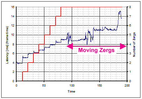
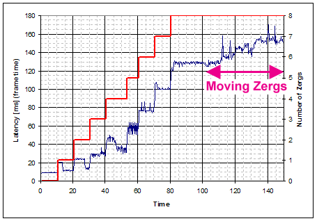
8 Zerg without sensors spawning in the DM-Mapping v3.1 map |
 |
 |
|
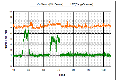
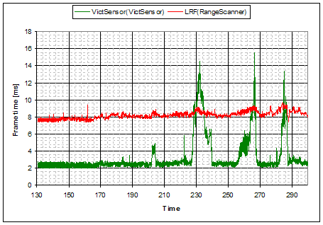
Laser and Victim Sensor computation time on DM-Mapping v3.1 map |
You can see how the 2 maps behave very differently.
DM-Mapping v3.01:
DM-Mapping v3.1:
Even if we assume that tV requires only 2ms, this is the resulting graph (1 laser and 1 victim sensor for each Zerg):
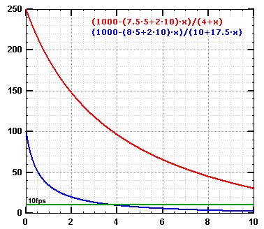 |
DM-Mapping v3.01 / DM-Mapping v3.1 (X: number of Zergs, Y: fps) |
All this is true only on my PC however. As I said before, parameters change widely from PC to PC. The following graph compares performance on 2 different machines (on DM-Mapping v3.1 map):
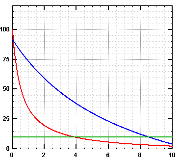 |
Intel Core 2 Duo 2.67GHz - 1.5Gb ram - Radeon 1600XT |
Just to make things more complicated, look at this graph:
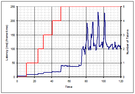 |
5 Talon without sensors spawning in the DM-Mapping v3.01 map |
You can see that with up to 4 Talon (still) the performance are good. If we add only another one the computation time rises a lot. And if we put them in motion the frame rate falls abruptly (latency increases).
These are only examples, you should make measurements on the competition PC using expected number of robots to find all the parameters.
Well, the only conclusion I can think of is that this equation doesn't solve anything :-) It only gives an approximate tool that, if used properly, can help to take some decision about the budget problem.
![]()