| PIC Projects Index | IK0WRB Site | Vinicio Coletti Site |
The controller card gets its power from the 6V lead accumulator that powers all the ship. Actually,
the voltage goes up to about 6.7 V for a full charged battery, so a series diode protects the PIC from voltage
inversions and drops the voltage by about 0.7 V. The PIC 16F84A should not receive more than 5.5 V
but I found that even at 6.0 V there is no problems, so the single diode is the unique regulation
of the input voltage.
The PIC oscillator is a classical 4 MHz crystal plus 2 capacitors, giving an istruction time of
1 microsecond.
The controller card has the following connectors and features:
The main purpose of the program on the PIC is to read the R/C pulses coming from the radio receiver, compute
the desired speed and produce adequate pwm pulses on the output, thus regulating motor's speed.
First of all, it's better to remind how an R/C command works. For example a 4 channel R/C command has 2 paddles
in it, able to move both horizontally and vertically (4 commands). The R/C transmitter reads the position of
every paddle, then sends the following sequence:
When a TTL input goes up, a PORTB interrupt on change is generated. The interrupt service routine
reads and saves the current Timer0 value, for future use. When the TTL input goes down, another
interrupt is generated and this time the service routine computes the difference with the saved value,
stores it and activates a validity flag.
In the main program loop, when a validity flag for channel 2 is detected, a routine reads the value
stored by the interrupt service routine, resets the validity flag, sets the motor direction (ON or OFF to
the switch output) and computes the pwm value.
When Timer0 goes in overflow (a 16x prescaler is used, so this happens every about 4 ms), if the pwm
is not zero the motor is started. In the main loop, when Timer0 value becomes greater than the
current pwm value, the motor is stopped. Thus the pwm frequency is about 250 Hz, certainly not the
best but to avoid this I should implement a different program logic and reduce the length of the
interrupt service routine to the minimum. Anyway it works.
Timer0 is also used to increment several "slow" counters, used in different parts of the program.
For example, when no PORT B interrupts are detected for about 1 second, this means that R/C signal
is missing, so the motor is stopped. The program then looks for new stable signals and if they come,
the normal computing is resumed.
To drive the motor output I use 4 pins of the PORT B in parallel, to have a driving current of
80 mA. This current goes to the base of a 2N3055 transistor, whose output goes to the bases of
other 3 2N3055, connected in parallel. I used this big-Darlington configuration simply because I had
available an used 4 x 2N3055 module, nicely mounted on a dissipating plate.
The very first version of the program had a serious bug: there was no total OFF of the motor when
the paddle was in the center position and there were always spurious max speed pulses. Debugging
was useless, until I went back to the Microchip manuals to read carefully how the "PORT B interrupt
on change" really worked. This way I discovered that when I switched ON or OFF the pwm output
(4 PORT B pins), I fired at the same time the interrupt, because every write to a port is also a
read from that port! Thus, the interrupt service routine was confused by all these false interrupts
and mixed wrong readings to the good ones.
Sadly, I already had the circuit mounted and tested when I discovered this, otherwise I would have
used a PORT A pin + a small transistor to drive the output. Thus, in the single point where the
motor is stopped, in place of a simple clrf PORTB instruction, I put the following:
Cheaper than another transistor, isn't it?
bcf INTCON,RBIE ; disables interrupts on PORTB clrf PORTB ; stops motor movf PORTB,f ; reads again PORTB to clear pins inequalities bcf INTCON,RBIF ; clears PORTB interrupt flag, if just activated bsf INTCON,RBIE ; enables interrupts on PORTB
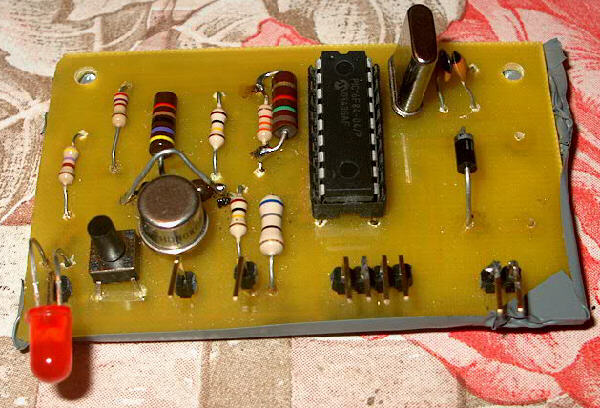
Outside the controller card
- 1x Microchip PIC 16F84 (or 16F84A), in the 18 pins DIP package
- 1x 18 pins DIP socket
- 1x 2N5320 transistor (or similar)
- 1x 1N4002 diode
- 1x red LED
- 1x white LED (hight brightness)
- 1x 4 MHz crystal
- 2x 27 pF capacitors
- 1x 56 Ohm, 1/4 W resistor
- 1x 62 Ohm, 1/2 W resistor
- 1x 470 Ohm, 1/4 W resistor
- 1x 810 Ohm, 1/4 W resistor
- 1x 4.7 KOhm, 1/4 W resistor
- 2x 100 KOhm 1/4 W resistors
- 9x connection points
- 4x 2N3055 transistors, mounted on a dissipating plate
- 1x 2 switches 30A relay (I used two separate relays of 3 x 10A each)
- 1x 1N5406 diode
| PIC Projects Index | IK0WRB Site | Vinicio Coletti Site |