|
|
|
|
|
rx-tx switch, transformer, transmitter |
mixer, filter, amplifier |
CPLD clock generator |
IW3IPD 137kHz QRSS RTX schematics
|
|
|
|
|
rx-tx switch, transformer, transmitter |
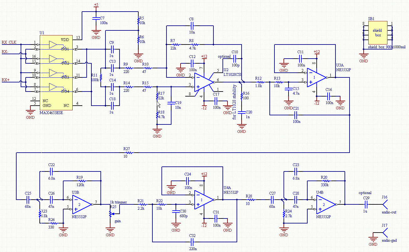
mixer, filter, amplifier |
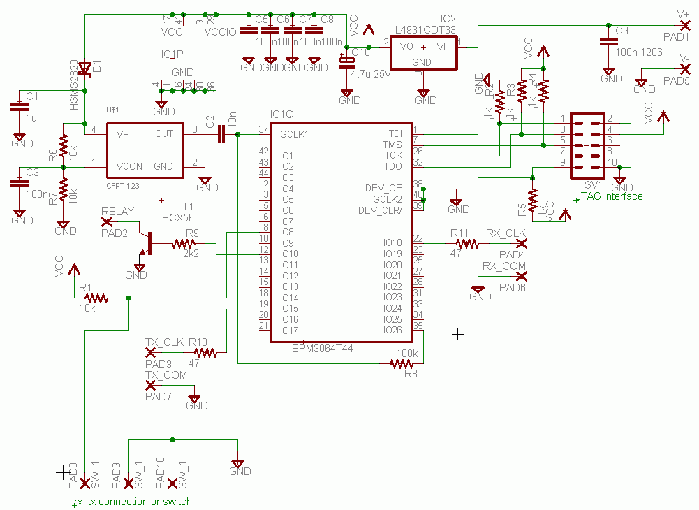
CPLD clock generator |
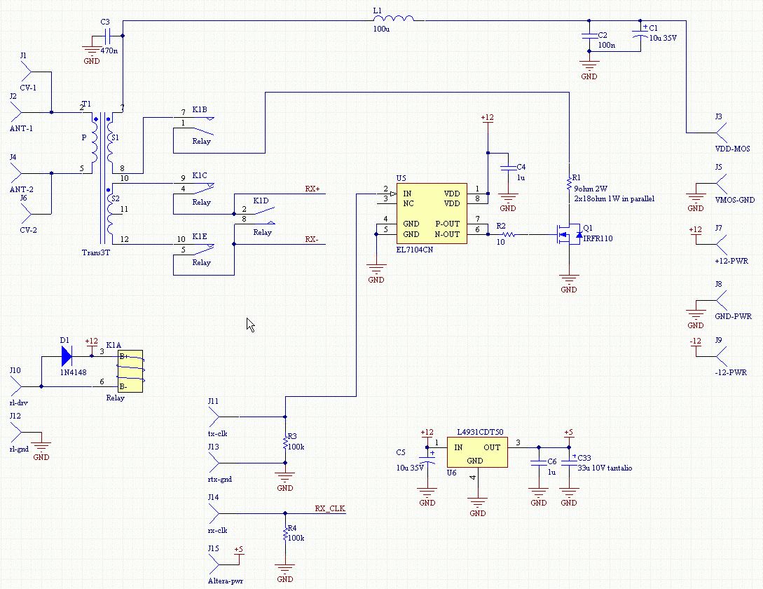
The first two schematics refer to the larger board (the RTX), while the third is the clock generator for TX (137.57kHz) and RX (135.4167kHz). The clock generator has two outputs RX_CLK and TX_CLK, connected to the corresponding inputs of the RTX, and an output RELAY connected to rl-drv input of the RTX. The last is used because the CPLD logic implements a small delay from relay actuation to TX drive (and from TX stop to relay release) to avoid unwanted leakage of TX power to the receiver. V+ power for the clock gen is +5V, taken from RTX J15. PAD8-PAD9 on the clock generator can be connected to a key or to the serial port of a PC: I use the program QRS 4.02 with the one-transistor interface suggested on its help. The interface is mounted inside the RS-232 DB9 connector.
The RTX has a main +/-12V power supply and a separate 12-18V power supply for the transmitter, according to the level of power wanted. I use a linear power supply taken from old surplus equipment, which uses a couple of 7812/7912 without heat sink. The transmitter supply is taken from the rectified input of the 7812.
The audio-out of the RTX goes to the audio line input of my PC. I use the same PC to receive with Argo and transmit with QRS.
About the circuit:
You will find a few resistors in series and capacitors in parallel: this is only because my collection of SMD components has a limited choice...
The relay used in the rx-tx switch is not very common: it has two NC and two NO contacts. I recovered it from a telephone switchbox board and adapted the schematic to it. To keep RX and TX isolated I used separate transformer windings for them, but this isn't a problem, because RX uses just 2 turns, while TX uses 1.
The transformer is an important component, because its primary winding is designed to almost resonate the antenna capacitance ai 137kHz and it must have low loss. A 10-80pF variable capacitor is connected to pins CV-1 CV-2 to find the exact resonance. The arrangement is well visible in the prototype photo. The ferrite core used is gapped (EPCOS RM12 core, N41 material, 250nH/turn) and gives an unloaded Q of around 420 at 137kHz. In my case the primary winding is 126 turns, giving 3.97mH; resonance at 137kHz requires 340pF, and in fact my antenna (with the cable) is 297pF: the remaining 43pF are given by some more cable to reach the receiver and the variable capacitor . I have measured the unloaded Q by replacing the antenna with two 150pF SMD C0G capacitors in parallel; when using the antenna, the Q reduces to 260, meaning that the total equivalent parallel resistance on the primary is 2πf*L*Q=888000Ω (this includes the effects of antenna radiation resistance, antenna loss and transformer loss). On the 1-turn secondary we have 56Ω, while on the 2-turns we have 224Ω. Clearly, the transformer is designed starting from the antenna and not the opposite, so if the circuit has to be replicated for a different antenna, this part of the design must be reviewed.
As you may have noticed, the mixer is not matched to the source impedance of 224Ω, but its input impedance is higher (around twice than that). This is intentional, because (with the LT1028) it gives a better noise performance respect to perfect matching.
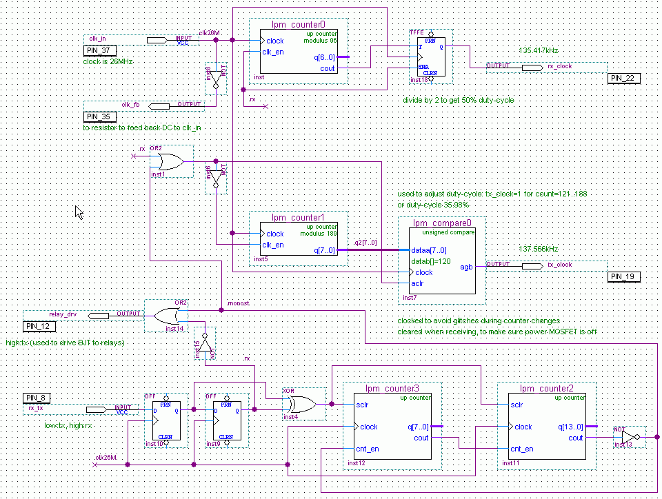
Passing to the clock generator, it uses a commercial VCXO simply because it was the most economical solution for me to get a 26MHz source. I found it on RS. As I already mentioned in the main page, I needed a clock that, once divided by an even number (to get 50% duty cycle), gave a clock near to 135.42kHz; 26MHz fulfill this requirement. The VCXO used allows a very small tuning range of +/-5ppm, useful only to discover received carriers coming from harmonic mixing products (because they move away -in frequency- faster than the adjustment). Here is a picture of the CPLD program, written with Altera Quartus II 7.1sp1 Web Edition. I programmed the chip with a homemade ByteBlaster interface.
