MG80C85
8-Bit Microprocessor

|
MG80C85 |
|
8-Bit Microprocessor |
Features
|
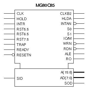
General DescriptionThe MG80C85 is an 8-bit microprocessor which features complete functional compatibility with industry standard 8085s and 8085As, and includes support for the special extended instruction set. Its design incorporates an onboard system controller, clock generator, serial I/O port and direct addressing capability to 64K bytes of memory. The MG80C85 utilizes a multiplexed data bus, with 16-bit addresses split between an 8-bit address bus and an 8- bit data bus. The MG80C85 is a macrocell building block for ASIC Logic design. Thus it can be used in conjunction with existing standard cell and gate array libraries to incorporate into original customer IC designs for lower overall system costs. |

| SIGNAL | TYPE | SIGNAL DESCRIPTION |
|---|---|---|
| A(15:8) | O | High Address Bus. The most significant 8 bits of the memory address. A(15) is the MSB. |
| AD(7:0) | I/O | Low Address and Data Bus. The low order memory address bus multiplexed with the data bus. |
| ALE | O | Address Latch Enable. This signal occurs during the first clock state of a machine cycle. |
| CLK | O | Clock. The period of CLK is twice the period of the CLKBY2 input. |
| HLDA | O | Hold Acknowledge. Indicates that the CPU has received the HOLD request. |
| HOLD | I | Hold Request. Indicates another master is requesting the use of the address and data buses. |
| INTAN | O | Interrupt Acknowledge. This active low signal indicates that the interrupt request input (INTR) has been recognized and acknowledged. |
| INTR | I | Interrupt Request. When INTR goes HIGH, it will inhibit the Program Counter, generate an INTA) signal, and sample the data bus for a RESTART or CALL instruction. |
| IO/M | O | Machine Cycle Status. See S0 and S1 status bits for further details. |
|
RDN, WRN |
O | Read and Write Control. These active low signals indicate that selected memory or I/O device is to be read or written to. They are high impedance during HOLD, HALT and RESET modes. |
| READY | I | Ready. This signal is set to HIGH during read or write cycles to indicate that the selected memory or I/O device is ready to send or receive data. |
| RESETN | I | Reset In. This active low signal sets the Program Counter to zero, and resets the interrupt enable (INTE) and HLDA flip-flop. |
| RO | O | Reset Out. Indicates that the CPU is being reset. |
|
RST7.5 RST6.5 RST5.5 |
I | Restart Interrupts. These inputs provide three maskable interrupts which invoke an automatic internal restart. RST7.5 is the highest relative priority, followed by RST6.5 and RST5.5. All three interrupts have a higher priority than INTR. |
|
SO,S1, IO/M |
O | Status Outputs. These signals provide an indication of the machine status during any given cycle. The status may be latched by the falling edge of the ALE signal. |
| SID | I | Serial Input Data. Data on this pin is loaded into accumulator bit 7 during a RIM instruction. |
| SOD | O | Serial Output Data. This signal is set or reset by the SIM instruction. |
| TRAP | I | Trap Interrupt. The highest priority non-maskable restart interrupt. |
| CLKBY2 | I | Clock by Two. This is the input clock source, used to drive the internal clock generator |
This soft megacell is in the ASIC Standard Library which is technology- and process-independent and is available in both Standard Cells and Gate Arrays.
A soft megacell is defined only at the schematic level. Each instance of the megacell has exactly the same functional definition; however, the physical mask layout is different for each instance depending on other functions being used, the place-and-route tools, and process technology. A soft megacell can be used with other megacells (including ROM and RAM) and logic from the ASIC Standard Library to build a complete system on a chip.
Contact the factory for more information.
Copyright © 1999 American Microsystems, Inc.