6C45-PE in Low Voltage Operations
You know, I'm a great enthusiast of the 6C45-PE. In this website you can find informations about it's use as driver for high power amplifiers based on big transmitting DHT triodes but also in low-power single stage amplifiers (both in Single Ended and Push-Pull mode).
However, I have discovered its excellence also in the low voltage domain making it a perfect choice for battery powered phono and line preamps.
Fig. 1, reflects this potentialities by comparing curves of 6Dj8 and 6C45-PE in low voltage regions (grid voltages are stepped by 0.1V).
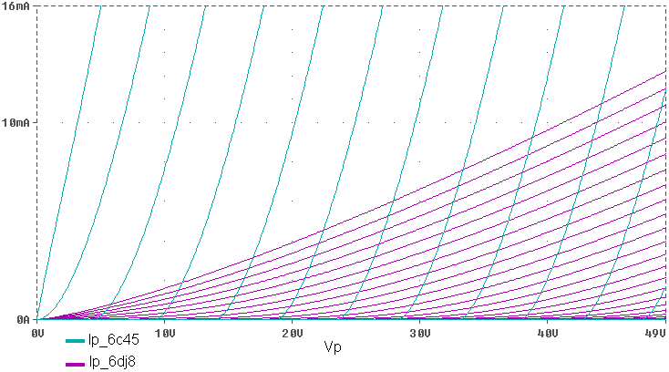
Fig. 1 6C45-PE vs 6DJ8 Plate Curves comparison
Hence, good linearity and high current delivery for extremely low plate voltages: a perfect situation for a line, battery powered preamp, Fig.2.
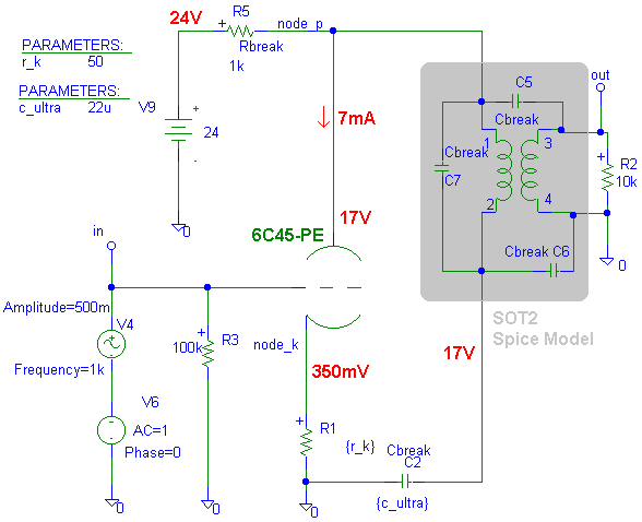
Fig. 2 Low Voltage Battery Powered Line preamp with the 6C45-PE (capacitor to ground connection)
In this schematic the voltage amplifation is possibile by R5 resistor. You can be tempted to use a resistor having an higher value or a choke. Unfortunately the exact load value (quantitatively and qualitatively) must be evaluated attentively in order to avoid a worsening of the response in the region of the low frequencies.
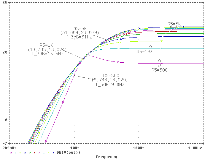
Fig. 3 Low Frequency Response with a purely resistive load for the preamp in Fig.2
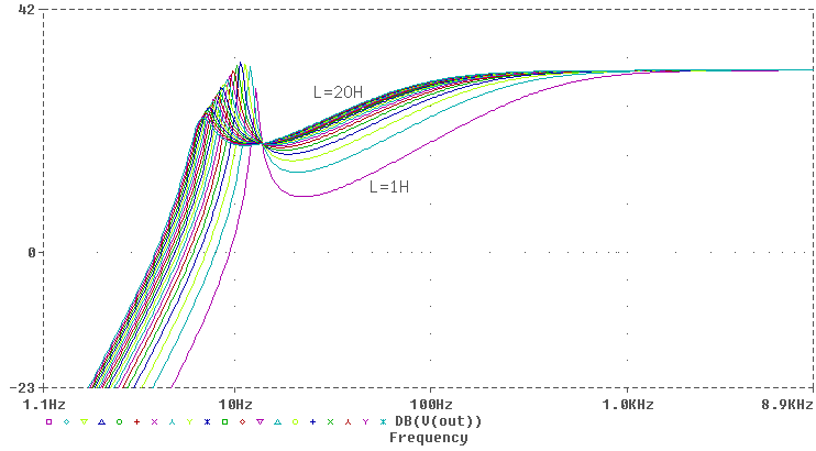
Fig. 4 Low Frequency Response with a choke load for the preamp in Fig.2
A purely resistive load of 1kW produce the best frequency response with a satisfying gain for a line preamp. Often you can find a circuit similar to the schematic in Fig. 2 where the capacitor is connected to the triode's cathode and not to ground , Fig. 5.
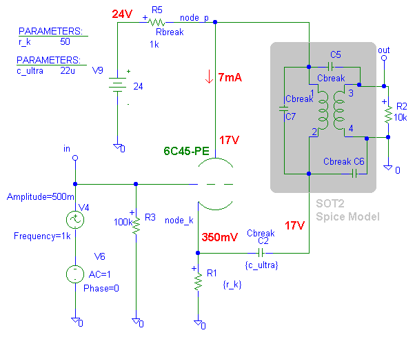
Fig. 5 Low Voltage Battery Powered Line preamp with the 6C45-PE (capacitor to cathode connection)
Simulations result in a better frequency for a same capacitor value for the Fig. 2 topology. In Fig. 6 is detailed the response in the low frequency regions for this different topology (capacitors connected to cathode). A good response is obtainable only for capacitors values greather than 15mF.
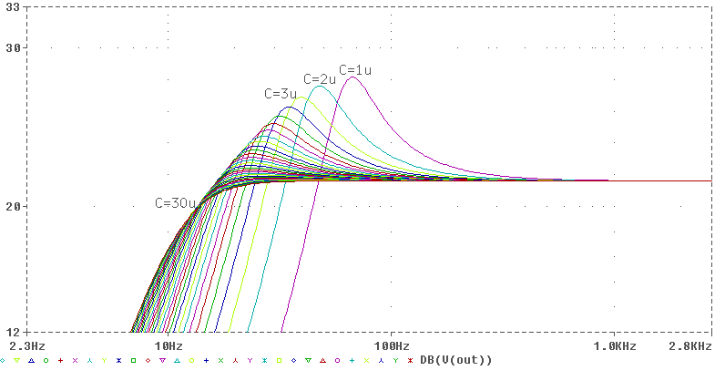
Fig. 6 Low frequency details for the capacitor to cathode connection
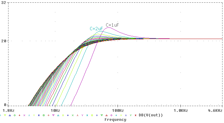
Fig. 7 Low frequency details for the capacitor to ground connection
On the contrary a good response for the schematic in Fig. 2 is obtained already for a capacitor of 5mF, Fig. 7. The bandwhidt, however, favors the capacitor-to-cathode connection due to an inherent local feedback.
....and what's about THD?
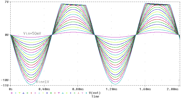
Fig. 8 Preamp Clipping Behaviour (capacitor to ground connection)
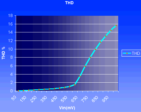
Fig. 9 THD vs. input signal amplitude- resistive load (capacitor to ground connection)
Simulations show that until the input signal amplitude don't exceeds 550mV (equivalent to 5,5Vout for the 20dB stage gain) THD is under the percentual unity.
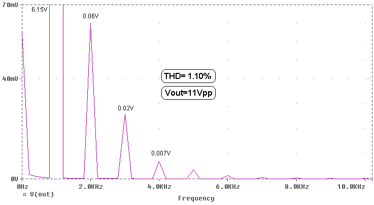
Fig. 10 Distortion Harmonics @Vin=550mV (capacitor to ground connection)
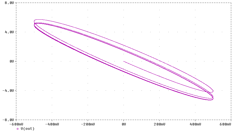
Fig. 11 Lissajous @Vin=550mV(100Hz) - Resistive+Capacitive (1mF) Load(capacitor to ground connection)
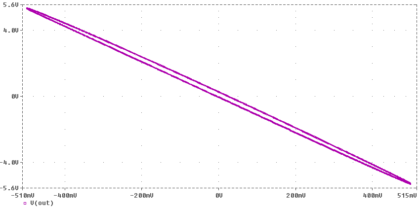
Fig. 12 Lissajous @Vin=550mV(1kHz) - Resistive Load(capacitor to ground connection)
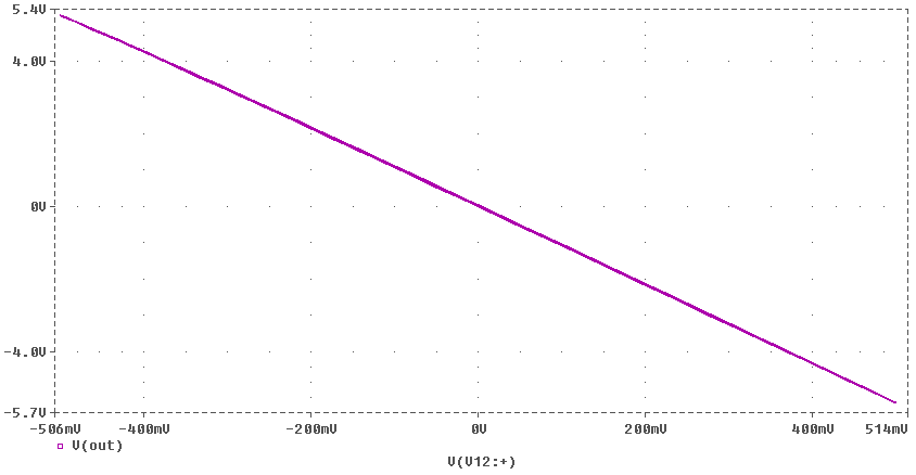
Fig. 13 Lissajous @Vin=550mV(10kHz) - Resistive+Capacitive (1mF) Load(capacitor to ground connection)
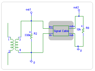
Fig. 14 Modelization for complex load interaction.
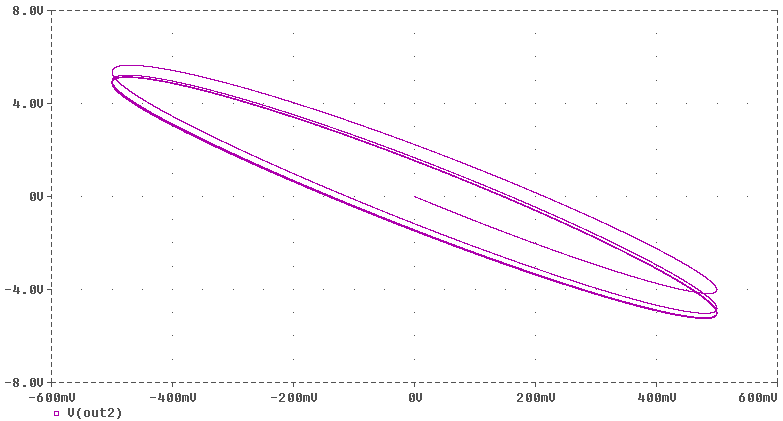
Fig. 15 Lissajous @Vin=550mV(100Hz) - Complex Load(capacitor to ground connection)
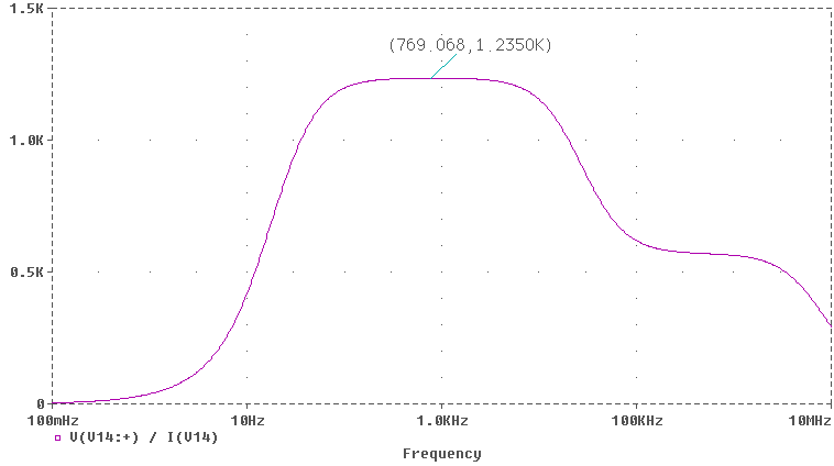
Fig. 16 Output impedance vs. frequency (capacitor to ground connection, 1:1 transformer ratio)
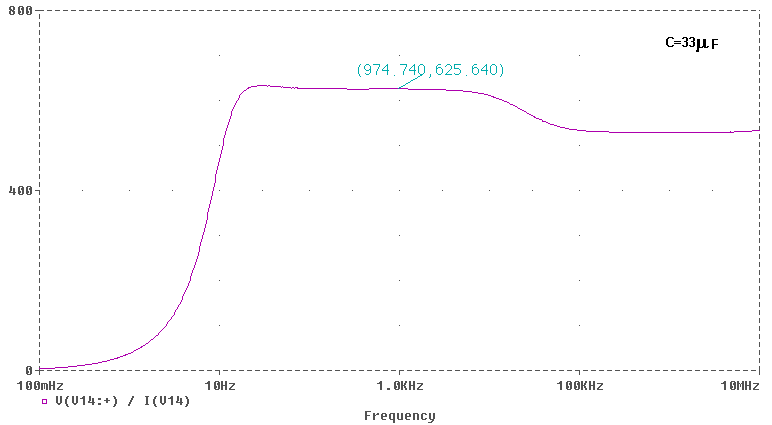
Fig. 17 Output impedance vs. frequency (capacitor to cathode connection, 1:1 transformer ratio)
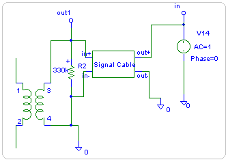
Fig. 18 Modeling for the Output impedance calculation ( 1:1 transformer ratio)
Again, the inherent feedback present in the capacitor-to-cathode connection improve the output impedance.
For this application I have found excellent the performances of the SOT2 transformer, a compact unit in m-metal core originally designed for Output Stage DACs.
|
What did you
think of this article? |