In Physics the word "current" means "the flow of particles through a certain surface over time".
For instance, standing on a bridge we can talk about the "current of the river", that means, we are referring to the particles of water that flow under the bridge as the time passes.
Therefore an Electric Current is simply the flow of charged particles over time. It is a flow of particles that have the peculiarity of being charged.
By calling "![]() "
the electric current we can write in a more compact way
"
the electric current we can write in a more compact way
![]() definition of the electric current.
definition of the electric current.
the unit of measurement of the current is C/s: we call this unit Ampere A=C/s.
We can produce an electric current using a battery and placing a metal wire between its terminals (plus and minus) in order to get a closed loop (a circuit). This way the electrons (negatively charged particles) can flow from the negative pole through the wire and join the positive particles stored at the positive terminal. The process goes on until the depletion of the reactants into the battery.
With such a circuit we short-circuit the battery and we discharge it very quickly. The only result of such an action is that we heat the wire.
If, on the contrary, we place an element in the circuit, (for example a light bulb) the battery lasts longer, because an element in the circuit provides a greater resistance to the flow of the particles.
In particular a bulb lamp consists of a thin filament through which the current passes. This filament restricts the amount of charge that can flow in the circuit, it represents a "bottleneck" in the circuit.
Because of the current forced into it, it gets very hot and emits light.
In general we can say that the amount of current that can flow depends strictly on the size of the wire: the thicker the wire the easier the passage of the current, because there is little resistance; the narrower the wire, the harder the passage of the current, because in this situation the resistance is higher.
As expected, the size of the current depends on the potential difference of the battery too. In fact, It’s the battery that provides the energy to push the electrons in the circuit.
The higher the voltage of the battery, the higher the current in the circuit and vice versa.
The law connecting all these facts is a proportional law. In the 1800’s Georg Ohm, discovered and stated that:
The current produced in a portion of wire by a certain potential difference, is directly proportional to the potential difference applied and inversely proportional to the resistance of the wire (Ohm’s Law)
If we label the "resistance of the wire" with the letter![]() ,
Ohm’s statement can be resumed by writing:
,
Ohm’s statement can be resumed by writing:
![]()
From a different point view Ohm’s law, provides a quantitative definition of the resistance of the wire:
In fact if we reverse the equation we get
![]()
that means resistance is the ratio of potential difference to the current.
Its unit of measurement is the Ohm ![]()
![]()
See the example in the text under the fig.13.6 on page 248.
In order to represent a circuit like the one in the figure, we can sketch its main components using standardized symbols.
The battery is sketched by drawing its two terminals: the longer line is the plus while the shorter and thicker line is the minus.

The bulb lamp and in general the resistors (components that provides a resistance to the passage of the current) are represented by a zigzagged line.
![]()
Electric wires are just straight lines, and we make the assumption they don’t provide resistance to the passage of the current.
The switch is represented by a break in the circuit: "closing the circuit" is equal to pushing the switch on and the net result is a current flowing. On the contrary, if the loop remains open the current can’t flow, (this is what happens when we turn the switch off).
See example 13.8 page 250 in the text-book.
In a circuit, we can insert more than one element one behind the other (See figure 13.9
in the text-book). This kind of circuit is called a series
circuit, because all the components are placed in a consequential chain along a
single loop arrangement. The same current passes through each component. The
higher the number of components in the series, the smaller the current flowing
through. This happens because the total resistance of the circuit increases. In a
series circuit if we have, for instance, three resistors with resistance ![]() the total resistance of the circuit is simply the sum of the single resistances:
the total resistance of the circuit is simply the sum of the single resistances:
![]() .
.
If we have more than one light bulb in the series, they glow less brightly than a single bulb, because the total series resistance is larger.
Another defect of such an arrangement occurs when a bulb burns out: when the filament of a bulb breaks, all the circuit breaks and also the other bulbs go out. This is undesirable, and it makes it very hard to find the burned-out bulb.
In order to avoid the previous problems we can connect the bulbs in parallel (see fig.13.10 pag.252 in the textbook). In a parallel circuit we have more than one loop, and the current splits up into different path.
The main features of a parallel circuit are:
As the textbook says
is the reciprocal of the sum of the reciprocal of each resistance, this yields a value less than any of the individual resistance(see the example on page 253 in the text-book).
The main advantages of such a circuits are:
The multimeter (fig. 13.11 page 254) lets us to measure the quantities involved in the physics description of an electric circuit like resistance, potential difference, and electric current. In effect it contains different instruments at the same time. By setting its function selector it can work as:
For the circuit in the following figure,
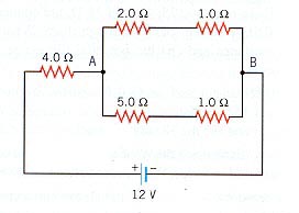
Find:
can be computed using the rules for the parallel and series resistances: by looking at the circuit we have
where
hence
.
so we conclude that
.
Some other interactive exercises can also be found at
http://www.clarkson.edu/~svoboda/eta/DCTutor/tutor2.html