![]()
![]()
![]()
![]()
![]()
|
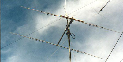
YAGI 2 el. for 24 Mhz, with linear charge
|
|
|
Now taken by the desire to test the effectiveness of the system
linear load a bit 'on all bands, I have ventured in the trial in
range 12 mt. We have already seen the 3 el. Yagi for 12/17 meters, where we know to be very simple construction and development, and now we see where you can keep an adequate mechanical strength, to shorten the elements and have an efficient antenna system anyway. So, we open the door again in our store and look in the middle of scrap aluminum tubing diameters needed to create the boom, the elements, insulators and wire-linear loads. If there was also a good baloon 1:1, maybe a few left inside the box, not go amiss. For the material used by the undersigned, refer to the antenna just above the 3 +3 YAGI for 12/17 meters that can be found on this site, and given that the system of isolation of the radiator are identical to this antenna I'm going to explain in details. For calculations of various measures on the 24 Mhz, the formula is always the same, with the only note that one must keep in mind that the shortening must be given to the element for the linear load. In essence, we will have an element radiator of 5.78 meters to shorten by 30% for the insertion of the linear load, but that it involves a stretching exercise.
|
|
 |
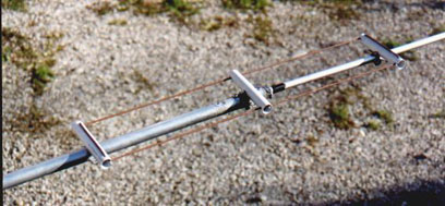
For those who want to enjoy making custom calculations, I refer you
the page of my Rotary dipole for 30/40 meters where spells the calculation system used. Those who are too lazy, the calculations are as follows: 1/2 wave minus 30%, for the length of the element, and 50% more will instead be the length of the linear load. For many experiments made on various bands, I found that the best position where to insert the linear load is half of semi-element. At this point we have 2 beautiful sturdy aluminum sections, with diameters 25 mm, which constitute the central part of the dipole, and a second part pool to be scaled with diameters between 15 mm and 10 mm (the latter only for the short and the final calibration). At the center of the semi-insulator element we have a very robust, diam. 23 full Teflon, drilled from one side to accommodate the outer element and no less than 20 cm long. It all depends on the robustness of this insulator element. For the practical construction of the linear load in the wire, once estimated the physical length of wire to be used (150 cm) will be passed to achieve the islands that will support (3 for each half-element) and measures load will consist of the size that will be provided to the load. I used PVC pipe electrician diameter 25 mm. and the pieces are 15 cm long. perforated so as to allow the wire to pass and get Live in implementing end. Course will be shaped in the center to be housed on the elements. The same block will be required for items with the plate bent to U aluminum 1.5 mm x 2 cm in width. |
|
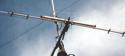
Metal clamps, however, will be used to assemble the
elements. At the end of construction mechanics, as mentioned above, put a baloon 1:1 heads of electrical connection of the radiator. To better understand some details of this antenna, landfill designs, measurements and some photos. ( Click here to see drawings ) Of course, the rewards from this antenna were not made to wait! But I leave you the pleasure of discovering the true potential offered by this antenna. Good work and good fun. |
|
|
|
|