The antenna (subtitle: the discovery of hot water!)
The space that the roof let go, after mounting the trestle and
my deltaloop triband, it was not so much and borders on the roof
with
the nearby .... too close!
So, in addition to the inevitable GP to 144/430, I was studying a
sys
but to have a certain directivity in 144 MHz with a gain.
Came from an experience of a builder Quagi 7 el.
long
3 meters and the results nothing short of amazing and not being able
to reassemble
I wanted almost the same results, but with a different antenna.
Browsing through the various texts and countless trade magazines, I
fell
5 el quad on the eye .
Has the characteristics necessary to install (lighter and
short) and text with interesting electrical characteristics.
And what 'was the result, and' a hybrid of all the texts I
bed taking a bit 'here and a bit' of the ', but ultimately what
count and 'it works or not?
The detail of this antenna, which in my opinion Interestingly, we
in the system that I have taken to assemble the elements, all
adjustable
separately, in order to obtain the best possible outcome and
enables the antenna to test all the possible optimizations.
We start from the boom, which are two pieces from each mt.1 from
diam.20 mm.
and 18mm aluminum.
The two parts are held together by a pair of self tapping screws
or cutting the head, across the board, the terms and diam.20 mm
then blocked with a metal band of appropriate proportions.
The boom, in my case, recovery is immensely round tube in my cellar
but if you do everything in picture is more 'easy.
The elements are
which will include a full rod diameter 6 mm (radial former glory
Fracarro) and one part diam.
8 (interno 6) vacuum tube aluminum.
Proceed for the construction of the elements: the proportion of rod
diam.6 servira'alla long part of the element, while the diam.
8 to
angles.
The 12 cm long and diam.8 will be cut as many as
are the angles that make up the items you want to build
(in my case, 20) all equal and all bent "very carefully"
the goal 'exact.
The result will be 'an angular cm.
6 x 6.
The tubes will all be cut transversely approximately 1 cm
forming an elastic mouth, then to tighten clamps
metal ends and inside which will be housed spare
full rod diam.
6 pre-cut.
The assembly mechanism will be 'in its simplicity' extreme and
robustness and durability, insured.
This method, as mentioned earlier, leaves the possibility '
antenna to experiment, then, any type of configuration
different.
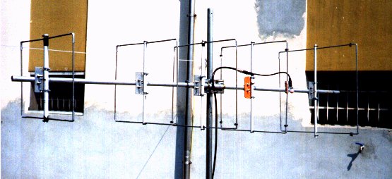
Then, the rectangle thus formed (in fact, are not elements
pictures!) are joined to the boom and from it through the insulated
pipes
PVC dia.
20 mm, a length sufficient to accommodate only 2 sides of
loop.
In my case the items were placed horizontally, except
radiator which form a square.
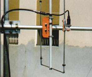
The power of course choice: in my case, vertically.
The radiator will go 'open on one side and shaped so as
accommodate the filler (the contacts must be very short).
The supports for the elements are a bit 'hard-working, but for those
who have special
welding machines or do not know obliging friend
equipped for metal, drill and hacksaw are being
still the only solution.
The tubes, cut more 'than 5 cm.
compared to the side of the element
you prefer, are drilled diam.5, 5 mm at the height
item that will have to go inside and it will be necessary then cut
transversely in the same head tube to the height of the hole
form an elastic loop that will close with a plastic collar,
after and was added to the item.
Approximately half of the tube in PVC
insert inside an aluminum tube with a diameter that can
light pressure and long about 15 cm.
This will serve not to deform the tube when we proceed to the
attachment
thus formed of the uprights on the boom.
The uprights will be fixed to the boom through the aluminum bracket
120 x 60 mm, thickness 3 mm., drilled in such a way as to stay the
metal clamps (2 for each bracket to about 100 mm) which will support
element, and 2 other holes diam.7 mm.
which will serve to pass
jumpers of threaded rod diam.
6 built on time and
bent always "very carefully", preferably hot.
Once all set to boom, to give a "team" general.
To calibrate the elements for the operating frequency of more 'in
keeping with the OM,
will loosen the metal clamps on the corners of the elements and
will shift inwards or outwards depending on the elements necessary .
In the end the result and mechanically extremely robust
with the possibility of fun to look for points of optimal spacing
between the elements, or agreement of the same, separately.
Electrically interposing a piece of 36 cm by 75 Ohm between element
Radiant and drop cable at 50 ohms.
Measurements: H (high), L (long), measured in cm.
LOOP
RIF l 62,8 cm h 54 cm (x 2) SPZ da RAD , 57 cm
RAD l 55,2 h 52 (x 2) SPZ da DIR 1, 36.5
DIR 1 l 53,2 h 45,3 (x 2) SPZ da DIR 2, 36,8
DIR 2 l 53,2 h 40 (x 2) SPZ da DIR 3, 52,2
DIR 3 l 53,2 h 35,5 (x 2)
The antenna I built and spacing so that I obtained,gave
very good results both in transmission and reception.
Will certainly not be an antenna with great performances, but in the
field
directives for small VHF I am sure it will give all using big
satisfactions.