(RPWS Links)
 The electric field sensor is made up
of three deployable antenna elements, an associated preamplifier,
and antenna deployment mechanism drive electronics. The antennas
are composed of interlocking sections made from beryllium copper,
and each antenna element is deployable separately to 10 meters
with its own 400-Hz a.c. motor. The electric field preamplifier
is used to add gain to the output signals from the antennas.
The antenna deployment mechanism electronics convert ±15
volt primary power to 400-Hz a.c. power for the antenna drive
motors.
The electric field sensor is made up
of three deployable antenna elements, an associated preamplifier,
and antenna deployment mechanism drive electronics. The antennas
are composed of interlocking sections made from beryllium copper,
and each antenna element is deployable separately to 10 meters
with its own 400-Hz a.c. motor. The electric field preamplifier
is used to add gain to the output signals from the antennas.
The antenna deployment mechanism electronics convert ±15
volt primary power to 400-Hz a.c. power for the antenna drive
motors.
 The magnetic search coil sensor assembly
is composed of a triaxial sensor assembly and an associated preamplifier.
The triaxial sensor consists of three orthogonal (i.e., perpendicular)
metallic alloy cores with two sets of windings each, one to produce
flux in the core and another to detect the flux. The magnetic
search coil preamplifier adds gain to the output signal from
the sensor assembly.
The magnetic search coil sensor assembly
is composed of a triaxial sensor assembly and an associated preamplifier.
The triaxial sensor consists of three orthogonal (i.e., perpendicular)
metallic alloy cores with two sets of windings each, one to produce
flux in the core and another to detect the flux. The magnetic
search coil preamplifier adds gain to the output signal from
the sensor assembly.
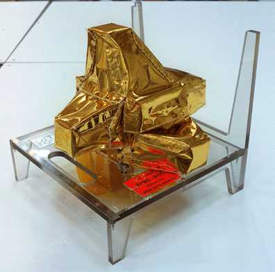
The Langmuir probe sensor assembly
consists of a 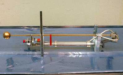 sensor, a preamplifier, and associated control electronics. The
Langmuir probe sensor is a 5-cm diameter sphere located at the
end of a rod approximately 1 meter in length. The sensor rod
is folded in a stowed state until deployed in flight. The probe
sensor preamplifier adds gain to the output from the probe.
sensor, a preamplifier, and associated control electronics. The
Langmuir probe sensor is a 5-cm diameter sphere located at the
end of a rod approximately 1 meter in length. The sensor rod
is folded in a stowed state until deployed in flight. The probe
sensor preamplifier adds gain to the output from the probe.
The RPWS main electronics includes a digital data processing unit, a high-frequency receiver, a wideband receiver, a medium-frequency receiver, a low-frequency five-channel waveform receiver, the Langmuir probe bias circuitry, and a power converter. For information on these components, click on their names.
(RPWS Main Electronics Links) The data processing unit (DPU) will control all instrument functions and will handle all communications with the orbiter. It will contain a large block of RAM to be used as waveform storage for the five-channel waveform receiver. Software in the DPU will be used to enhance the scientific return of the instrument by performing various analysis and data compression operations.
The high-frequency receiver is a digital waveform processor that operates by digitizing a portion of the bandwidth received from the electric field sensor antennas and deriving spectral and waveform vector information from the waveforms using digital signal processing techniques.
The wideband receiver will obtain very high-resolution electric or magnetic field waveforms for selected time intervals that vary from under a minute to as much as an hour or more. The receiver has two selectable passbands: 50 Hz to approximately 10 kHz and 10 kHz to approximately 80 kHz. The wideband receiver uses high-rate telemetry to transfer waveform information in a given bandwidth from a selected sensor directly. The input signal is selectable from one of five inputs: two electric, one magnetic, a frequency-converted output from the high-frequency receiver, and the Langmuir probe.
The medium-frequency receiver provides spectrum measurements over the frequency range from 25 Hz to 12.6 kHz. This receiver is attached to one of four sensor inputs (two electric and two magnetic) and uses double frequency conversion to convert the input bandwidth down to a low-frequency constant frequency band, where it is detected by an amplitude detector.
The low-frequency five-channel waveform receiver provides high-resolution spectral measurements of electric and magnetic fields over the frequency range from 0.1 Hz to 2.5 kHz. It provides simultaneous waveforms from all five antennas (three magnetic axes and two electric axes). This receiver captures blocks of waveform data simultaneously from the five sensors and maintains a high-degree of phase and amplitude accuracy. The data is processed through five parallel amplifier and filter channels.
The Langmuir probe bias circuitry...??(more to follow)
The power converter converts d.c. power from the spacecraft power supplies to a.c. power to operate the instrument. The conversion frequency will be fixed at 100 kHz by locking onto a signal from the spacecraft bus interface unit.