There are around 3 million people suffering from epilepsy in Europe. Many of them need to be monitored to exactly identify the brain region where the epilepsy sets, when surgery is the last chance. However, epileptic seizures happen without any warning or with weak trigger signals (under investigation) and sometimes the inter-ictal period, which is the time between two adjacent seizures, is very long. For this reason long EEG (electroencephalogram) recordings must be done to capture these rare events: EEG must be recorded continuously for days and with many electrodes. Even if these recordings are made, generally, in hospitals, designers of these special recorders need to achieve the most comfortable solution for the patient, to let her/him live as free as possible as the "waiting time" could be quite long.
Introduction: basic Neurophysiology for engineers
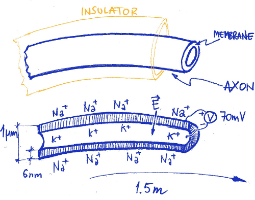
The human brain is an extremely complex network of neurons (around 100 billion, 1011) connected with 1014 wires (synapses). Each cell has its own electric activity which is triggered by the neighborhood. Peripheral neurons have long wires (axons) bound at the far end to specific receptors, suitable to detect different stimulus (heat, pressure, pain, etc.), or to actuators to muscles or to other body parts. These neuron extrusions are long up to 1.5m and thick as 1µm, like the sciatic nerve from the spinal cord to the feet, and transmit the low electrical signal from/to the brain without loss and at high speed (~50m/s).
Differently from what is commonly believed, the signal transmission is not performed by the internal of the axon. Instead, it is the membrane which perform this magic activity in a very efficient way.
Inside the body, we do not have conductive copper-like wires: everything is managed by a complex (and quick) ions exchange in and out the axon membrane.
Figure 1. Axon conduction: the conduction of electrical pulses to and from the brain, is not made by a conductive wire as we are used to think. The transmission of the electrical information is performed by the axon membrane. In rest conditions, the internal of the axon is filled with positive Potassium ions. The outside of the membrane is surrounded by Sodium ions, also positive. The electrical rest gradient of -70mV (inside with respect of outside and due to different ions concentration) is sustained by the membrane, which is a good insulator. However this is an active insulator and, if electrically triggered, it lets the Sodium ions to enter in and the Potassium ions to go out, changing the voltage polarity across the membrane. After the shot, thousands of mechanical pumps push the Sodium ions out again and take the Potassium ions in, consuming the ATP (Adenosine-TriPhosphate) fuel and resetting the Na-K gradient. The membrane in rest conditions is a sort of loaded spring, ready to snap. The electrical shot can propagate triggering the side section, like a domino, at relatively high speed all along the axon membrane.
EEG signal is generated inside the brain from the electrical activity of cells (neurons). A typical neuronal membrane electrical shot is a signal which amplitude peak to peak is about 110mV with a duration of about 3ms: the Action Potential.
Despite of the low electrical voltage through the membrane, its extreme thinness (6nm) requires a very high dielectric strength: cell membrane must sustain an electrical field up to 106V/m, a very good insulator indeed.
During normal awake brain activity, a crowd of 1011 neurons speak together inside the brain. As the brain is protected by an anti-shock liquid-filled bag and by a resistant skull, when we need to check for the electrical activity of the brain (the EEG) without invasion, we have to detect the signal from outside. The information that comes out is very weak and confused, low frequency filtered and jammed. Looking at the EEG signal from the scalp is like to watch a beautiful landscape through a frosted glass.
Figure 2. The Action Potential is generated through the cell membrane each time the sides are depolarized above -55mV. If one section is stimulated, the discharge will propagate quickly to the neighborhood. The potential will propagate on one direction only because, after the discharge, each section remains blinded (undershoot) for a small time interval. During this phase, the refractory period, the membrane cannot discharge again (unless the re-triggering potential is higher than the first).
A typical adult scalp EEG signal ranges from 10µV up to 100µV and has frequency components from 0.5Hz to 100Hz. It appears as a noise as a very large number of 110mV deep sources shots sum up to the global signal.
When awake and open eyes, no shots synchronization appears from outside and the EEG is like a large band noise. But if the eyes are closed, immediately in the posterior part of the scalp (the occipital region), a clean ~9Hz signal appears: the Alpha Rhythm. This is an easy test that hardware designers can perform on them self to check for EEG recording device proper functionality and performance. Normal awake brain activity is, hence, almost random noise.
Epilepsy and EEG
Epilepsy is a quite common brain disorder. During certain epileptic seizures, a sort of strong self-sustained oscillations appear inside the brain. Generated by a group of neurons, these oscillations disrupt the normal activity of a large number of other neurons, de-facto seizing the functioning of the brain. The reason of these oscillations is still under investigation but they can be triggered in many ways: by flashing light (very commonly), by movements (e.g. chewing) or even by mathematical thought! However, sometimes they just happen and, at the moment there is no way to predict when; unfortunately, sometimes there are also no drugs to contrast the seizure.
This is the worst case, when surgery is the way out. If the region of the brain which generates the seizure is quite small, it may be removed and the problem may be removed, too.
To exactly identify the epileptogenic region, a number of exams and measurements on the brain must be done. Scalp and intracranial (deep) EEG are some of these.
In the past years, a number of researchers have been involved to identify possible electrical markers in the EEG signal between seizures, to predict the seizure incoming, giving enough time to the patient or to her/his parents and take appropriate actions to stay as safe as possible. Many people suffering from epilepsy could have a normal life between seizures but they can't, because they simply don't know when these happen.
During the European Project EPILEPSIAE[2] we tried to set the basis for a seizure prediction approach, hardware and software.
Specifically, during this project, we were challenged also in the design of a wearable high performance device for long term EEG recording of hospitalized and ambulatory patients, for research but also for routine exams.
EEG-Recorders
To build a medical device, and specifically EEG recorders, an accurate risk analysis must be carried out before starting. As usual, it is much more convenient to adjust specifications rather than to over-patch the prototypes.
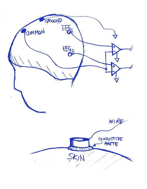
A typical configuration for EEG scalp recording, requires the use of a number of differential amplifiers, generally referenced to a common neutral potential.
To improve the acquisition quality, a special conductive paste is used between the electrode and the skin. This paste reduces the contact impedance and reduces the movement artifacts.
Surface electrodes need to be fixed on the scalp with caps or strings.
Figure 3. Typical acquisition setup (only two electrodes are shown). Differential, high impedance, low noise amplifiers are used to get the faint signal from the brain activity. Physicians are interested in EEG1-EEG2 signal and not to EEG1-Common, EEG2-Common. This adjustment is performed on-line by the host computer. Specific saline conductive paste is used to improve the contact impedance with the skin: it is put between the electrode (usually Ag-AgCl) and the skin.
To record the EEG signal from scalp it is common to use a low-noise differential amplifier, followed by a high resolution AD converter. The amplification channel has a gain which depends on the AD resolution and allowed dynamic range in the input [1].
It can be think that, as the typical EEG signal is around 200µV pk-pk, a dynamic range of 1mVpk-pk could be sufficient. However, as patient is generally free to move in different environments, high voltage artifacts may be experienced and many hundreds of mV dynamic range is needed to guarantee a correct acquisition of EEG signal even in worst conditions without saturation. This is especially important for wearable devices.
A 24bit AD converter can manage a 200mVpk-pk signal with a resolution of 12nV/step!
The background noise from the amplifier sets the lower limit for the resolution. The larger the bandwidth, the higher the noise. Generally a commercial 500Hz analog bandwidth channel can have a background noise ranging from 1µV to 5µV peak to peak, depending on front-end technology.
A high level EEG acquisition system (wearable) can manage up to 64 channels, simultaneously sampled at a rate of up to 2048sps and 24bit/sample, working at least 12hrs on batteries (home night recording on a reduced electrode number set).
Even if data are safely stored into a local large memory and downloaded at the end of the acquisition exam, it may be necessary to monitor the patient status in real time, for example to check for electrode-skin impedance. In fact, it is quite usual that after some hours some electrodes disconnect from the scalp and the EEG signal is lost or corrupted. For this reason an on-line wire and wireless connection could be an extremely important feature. If the patient is wire connected to a remote host, many safety precautions must be taken to keep the system safe from electrical hazards. Multiple isolation levels must be included in the power supply and data paths, according to the international safety standards. The wireless solution allows an easier management of the electrical risks, however important issues must be considered to manage the RF energy levels in proximity of the body and the communication safety and reliability.
As a general rule, the data acquisition can never rely exclusively on the wireless channel.
When energy budgeting is a serious issue, an accurate selection of the wireless technology to be used must be performed: many constraints work together and narrow the road of possible choices.
Sometimes it is preferable to use mature, widespread technologies rather than the newest ones considering, however, that medical devices must be maintained and spare parts provided for repairing, for years after the product shut down. The bandwidth availability, the power efficiency, the integration with the IT infrastructure and the development cost and time show the solutions: at the moment (2014) the technologies are Bluetooth and WiFi [3].
A 32channels system, sampled at 2048Hz with 24bits/sample, requires at least a net 2Mb/s (data+guard and recovery) communication channel. Standard, medium power version 1.2 Bluetooth (60mA-TX @ 3.3V) cannot guarantee this throughput. WiFi can do better but requires more power and the batteries will have a shorter life.
Generally the patient is wireless monitored just for short periods when cable is not available, not for the whole session. In these periods, data need to be sent to the wireless channel but buffered also into internal memory. If the link is lost due to the out of range, as soon as the link is back, buffered data will be sent to the host.
Selected average power Bluetooth radios can provide around 500Kb/s data-rate within some meter range in a reliable way (data bandwidth is larger but margin is needed). This means that only 20 EEG channels, sampled at 1024Hz with 24bit resolution, can accommodate in the Bluetooth channel; this is sufficient in many EEG applications but just for monitoring purposes. Raw data, with full bandwidth and resolution are always stored in the device internal memory and downloaded at the session end. In this way no information is lost.
A typical problem that arise during the monitoring of ambulatory patients is the acquisition compatibility with a lot of high noise sources.
It is commonly desired that during long term EEG acquisition, patients can use mobile phones, browse the internet (possibly with a wireless connection also!) and move freely. This can induce wide artifacts in the acquired signals and appropriate countermeasures must be taken considering that the useful signal is only few hundreds microvolts. This goes often well beyond the compliance with the international EMC rules. For example, the EM immunity test, according to medical standards (IEC 60601-1-2) requires that the functionality of the device is guaranteed under a modulated EM field of 3V/m.
The CMRR (Common Mode Rejection Ratio) problem
Another parameter that is often evaluated during the design of bio-amplifiers is the CMRR. The major concern is generally related to the noise coming from the 115/230VAC power network. A pervasive 50/60Hz sinusoidal signal is always present around the patient and this signal is induced equally in the whole body which moves, electrically speaking, with respect to the ground. This is an important issue but it must be considered that this induced signal can be detected and it interferes only if a reference to the earth is available. A floating amplifier with differential inputs and referenced to the patient body is intrinsically highly immune to this disturbance. A different behavior appears if the amplifier has an earth loop, capacitively coupled, through the communication link or through the power supply, to an earthed host.
The best the amplifier reference is electrically glued to the patient body and isolated to the power grid, the less critical is the CMRR, at least in relation to the induction from the mains.
It is preferable to not have hardware 50/60Hz notch filters in the amplification chain but to have large dynamic acquisition range and use digital filtering during data processing.
Wearable, battery powered devices, with local memory storage and wireless link, have the best CMRR performances.
However, the CMRR is not related only to the induction from the mains. All the signals that appear to both the differential inputs of an amplifier are rejected with a finite ratio.
Figure 4. An ideal differential amplifier rejects common signals that are present to both inputs (VP, VN). However, real amplifiers have a limited power to perform this function. CMRR is a measure of how good is the amplifier to remove these common signals. The higher this value (generally expressed in dB), the better the performance.
Besides of the AC power supply, there are common mode signals that can arise with respect to the amplifier ground. If the input impedance of the amplifier is not high enough with respect to the signal source impedance, we get an attenuation of the bio-signal. Typically, the source impedance may vary from some KOhm to hundreds of KOhm and consequently the bio-amplifier input impedance must be as high as 10MOhm to 500MOhm. But this is not a big issue until both the differential amplifier inputs show an equal behavior. However, if the source has a differential impedance, a common signal becomes differential and appears to the output as an artifact. This is quite common when the patient moves and the electrodes are not well fixed to the skin or the conductive paste, used to improve the contact impedance, dries differently from electrode to electrode: ghost slow frequency signals may appear to the traces.
Input bias current can also transform impedance differences between inputs, into differential voltage to the output (see figure 4). The less the bias current, the best the performances during ambulatory acquisition.
Acquisition system
To build a practical device, all the issues (safety, usability, feasibility, etc.) need to be considered. Often there are constraints that fix some features limitation: the safety set the bar.
A typical bio-recorder for Long-Term EEG acquisition is made of different blocks, all highly optimized for power efficiency: in a sample clinical application the power budget is limited to 450mW for a 64 EEG channels system @2048Hz sampling rate each (see block schematic in figure 6).
Figure 5. Typical blocks schematic of a Long-Term EEG wearable recorder.
To keep the power consumption as low as possible, the system clock is reduced to the minimum and the firmware is developed at low level to improve the execution speed efficiency. Many functions can be performed by an FPGA (Field Programmable Gate Array, a hardware programmable device) to relieve the microcontroller from time critical tasks. The system chooses the appropriate interface to send data (priority is the wire) but the primary storage is the local flash memory, large enough to keep all the recording session data.
Figure 6. An example of an analog channel schematic
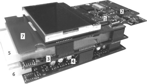
Figure 7. An example of recorder circuit boards amplifier: 1) Bluetooth module, 2) SD-MMC slot, 3) Analog board, first 32 channels, 4) Analog board, second 32 channels, 5) 6) Input connectors, 7) Digital board.
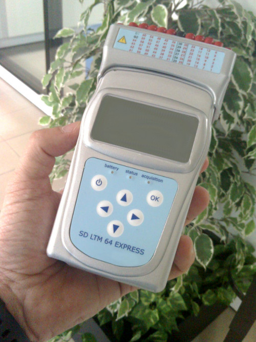
Figure 8. A wearable commercial grade Long-Term EEG recorder. It can record up to 64 EEG channels sampled at 2048Hz each (expandable to 256 channels-4 synchronized units) for more than 10 hours. Extra DC channels are provided for external sensors. Internal accelerometers provide information on motion and patient posture. Bluetooth link provides the short range wireless connection.
Conclusions
In the past decades we have seen a progressive reduction in size and energy requirements of medical devices, especially for bio-recorders. These factors opened two ways: a true wear-ability and a terrific increase of performances. This gave to researchers and clinicians the opportunity to collect a huge amount of data from the patients in near real-life conditions and also to reduce the hospitalization and general costs. This trend will continue in the future with the availability of new wireless technologies and the integration with mobile communication infrastructures and IoT (Internet of the Things).
It is the bio-engineers challenge for the future to keep these technologies feasible and safe for medical applications
Aknowledgments
EPILEPSIAE project (2008-2011) was financed by the European Community under the seventh framework program (FP7-G.A. 211713).
References and Notes
1.Cipriano Castellaro, Gianpietro Favaro, "Hardware for Seizure Prediction: Towards Wearable Devices to Support Epileptic People", Engineering in Medicine and Biology Society, EMBC, 2011 Annual International Conference of the IEEE, DOI: 10.1109/IEMBS.2011.6090470, 2011 , Page(s): 1628 - 1631
2.Antonio DOURADO, Michel LE VAN QUYEN, Björn SCHELTER, Gianpietro FAVARO, Francisco SALES, Vincent NAVARRO, Andreas SCHULZE-BONHAGE, "EPILEPSIAE- Evolving Platform for Improving Living Expectation of Patients Suffering from IctAl Events", The Fourth International Workshop on Seizure Prediction, June 6, 2009 , Kansas City, USA. http://www.iwsp4.org/posters.htm
3.Note: a very interesting article is published by the U.S. Food and Drug Administration (FDA) on Wireless Technology in Medical Devices.
Link to:
FDA-Guidelines