GDF 1K2 1,2KW HF + 6m Solid State Power Amplifier
For info in English contact
me, thank you
Amplificatore
lineare, o semplicemente lineare
...ma perchè "lineare"?
Rispondo
riportando quello che troviamo nello ARRL HANDBOOK:
[...] The amplifiers commonly used by amateurs for increasing their
transmitted power are often referred to as “linears”
rather than amplifiers or linear amplifiers. What does this mean and why is it
important?
The active device in amplifiers, either tube or transistor, is like a
switch. In addition to the “on” and “off” states of a true switch, the active
device has intermediate conditions where it presents a finite value of
resistance, neither zero nor infinity. As discussed in more detail in the RF
Techniques chapter, active devices may be operated in various classes of
operation. Class A operation never turns the device fully on or off; it is
always somewhere in between. Class B turns the device fully off for about half
the time, but never fully on. Class C turns the device off for about 66% of the
time, and almost achieves the fully on condition. Class D switches as quickly
as possible between the on and off conditions. Other letters have been assigned
to various rapid switching methods that try to do what Class D does, only
better. Class E and beyond use special techniques to enable the device to make
the switching transition as quickly as possible.
During the operating cycle, the highest efficiency is achieved when the
active device spends most of its time in the on or off condition and the least
in the resistive condition.
For this reason, efficiency increases as we go from Class A to B to C to
D.
A linear amplifier is one that produces an output signal that is
identical to the input signal, except that it is stronger. Not all amplifiers
do this. Linear amplifiers use Class A, AB or B operation. They are used for
modes such as SSB where it is critical that the output be a close reproduction
of the input.
The Class C amplifiers used for FM transmitters are not linear. A Class
C amplifier, properly filtered to remove harmonics, reproduces the frequencies
present in the input signal, but the envelope of the signal is distorted or
even flattened completely. (See the Modulation chapter for more information on
waveforms, envelopes and other signal characteristics.)
An FM signal has a constant amplitude, so it carries no information in
the envelope. A CW signal does carry information in the amplitude variations.
Only the on and off states must be preserved, so a Class C amplifier retains
the information content of a CW signal. However, modern CW transmitters
carefully shape the pulses so that key clicks are reduced to the minimum
practical value. A Class C amplifier will distort the pulse shape and make the
key clicks worse. Therefore, except for FM, a linear amplifier is recommended
for all amateur transmission modes.
Some digital modes, such as RTTY using FSK, are a form of FM and can
also use a nonlinear Class C, D or E amplifier. If these signals are not clean,
however, a Class C amplifier may make them worse. Also, Class C or even D and E
can be used for very slow CW, for very simple low-power CW transmitters or on uncrowded bands where slightly worse key clicks are not so
serious. After all, Class C was used for many years with CW operation. [...]
Magari
era chiaro per tanti, ma non per tutti.
Passiamo
alla descrizione.
In
passato ho lavorato con le valvole, sempre con ottimi risultati. Le valvole
hanno tanti pregi, sono quasi indistruttibili, direi che mai (o quasi) nessuno
di noi abbia sentito "ho bruciato una valvola!"... cosa, tuttavia,
probabile con i transistor. Anche i transistor hanno i loro lati positivi...
primo fra tutti che non necessitano di tempo di accensione, poi, nessuna
taratura per cambio banda è necessaria, ...e tanto altro.
Io
non ho tantissimo tempo da dedicare alla radio, non appena mi siedo ho
necessità di essere subito "operativo". Lo stato solido fa al caso mio. Inoltre volete non considerare la
comodità di cambiare banda all'istante? Se date un'occhiata al mio log, troverete
contatti consecutivi in bande diverse, per esempio un dx
in 15m e subito dopo uno in 40m, poi ancora in 10m...
Bisogna
provare ...e poi difficile tornare indietro.
Sin
da subito mi sono reso conto che progettare da zero un amplificatore RF era da
pazzi, lì nel mondo ci sono tanti che lo hanno già fatto, quindi approfittiamo.
Come
hanno fatto un po' tutti sono partito dal progetto EB104.
Gli
americani di Communication Concepts, Inc. lo
vendono in kit. Acquistai due pezzi più uno splitter/combiner 2 vie.
Il
problema era l'alimentatore: 48V 50A non era semplicissimo da realizzare. Gli switching non erano affatto economici, quindi mi buttai sul
classico trasformatore.
Comprai
da RS-Component un paio di trasformatori toroidali da
40V 25A e li misi in parallelo, qualche transistor come regolatore e... via.
Dicevo, non era semplice. Con carichi improvvisi di soli 20A i transistor
saltavano, ho provato di tutto ma la differenza di potenziale di 50V era
troppa, bisognava progettare seriamente un alimentatore lineare. Mi venne
l'idea di utilizzare degli SCR con raddrizzatori e regolatori, funzionava bene
...però era tutto molto rumoroso, sulle bande basse mi appariva sul panadapter un segnale "alieno", ma era
terribilmente terrestre, anzi di casa mia.
Quindi
switching avevi vinto.
Tuttavia
l'alimentatore non era il solo problema.
Lo
EB104 non era poi così performante: in
basso andava bene, ma già in 12m tagliava terribilmente. In 10m non riuscivo a
tirare più di 400W a modulo...
L'immagine
successiva riporta una foto:
Non
ha avuto mai la fortuna di essere inserito in un contenitore: non l'ha
meritato.
Tuttavia
soddisfazioni me ne ha date tante, molti new-one li
ho lavorati grazie a lui.
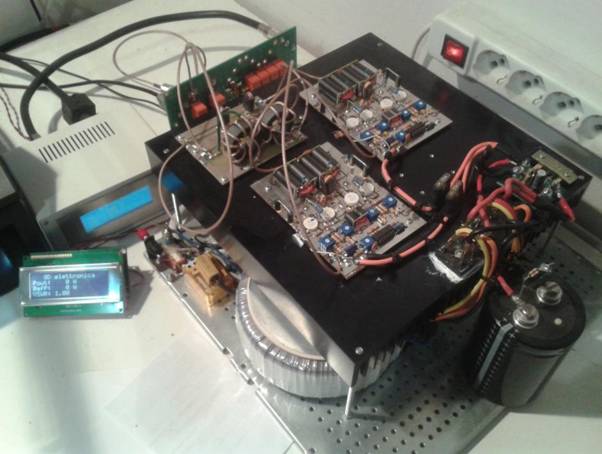
Dando
un'occhiata sul web, ho trovato un'azienda greca che produce "pallet
amplificatori": RF-Source..
Dopo
un paio di mail ho deciso di prendere 4 moduli da 300W PHV305 e uno Splitter/Combine a 4 vie CH2004.
Davvero
ottimi e ben costruiti... e soprattutto erano forniti montati e collaudati. Io
ho provveduto solo a sistemarli sul dissipatore e a connetterli allo splitter/combiner.
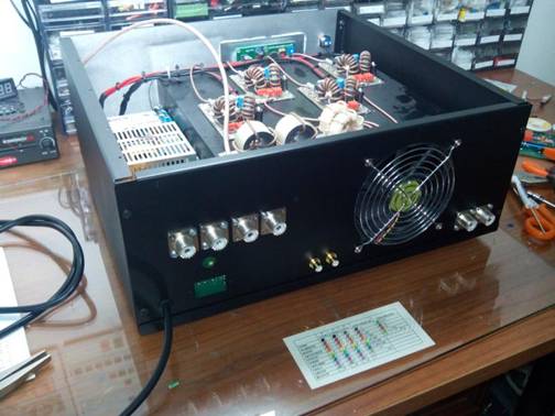
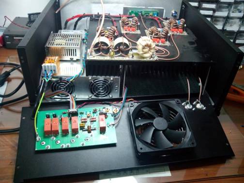
Come
si intravede dalle foto c'è un grosso alimentatore, quello che per troppo tempo
ho evitato di comprare. Si tratta di un MEAN WELL da
48V 50A modello RSP-2400-48.
L'alimentatore
più piccolo sistemato sopra, è uno da 12V, utilizzato per i
"servizi".
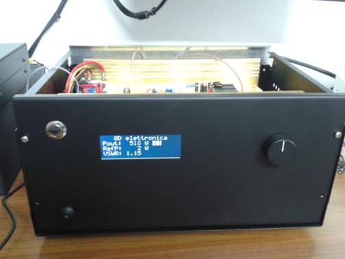
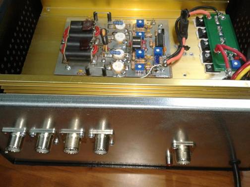
Il
lineare è nudo e crudo, nessuna protezione (per il momento). Ho inserito un wattmetro-rosmetro con display LCD, un commutatore per 4
antenne (con possibilità di usare in ricezione un'antenna e in trasmissione
un'altra) e un commutatore per due ingressi rtx.
Per
ora sto lavorando sui filtri passa-basso d'uscita e
la gestione del cambio banda via CAT.
Alcune
foto:
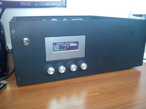
Ammetto,
il pannello frontale non è bello ...qualcuno mi ha detto è quasi
"funebre".
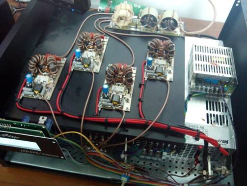
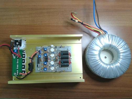
Foto
durante la realizzazione (notare lo splitter sotto il
dissipatore, il wattmetro-rosmetro con PIC):
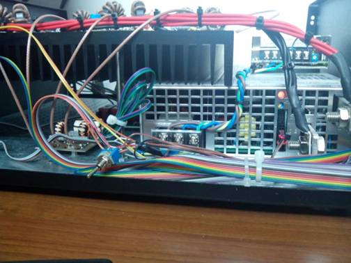
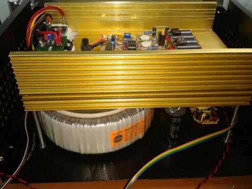
In
realtà una piccola protezione è già presente:
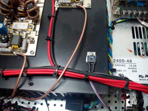
Si
tratta di uno switch termico (termostato) che stacca
tutto non appena il dissipatore arriva a temperatura di 70°.
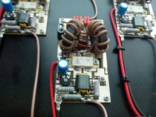
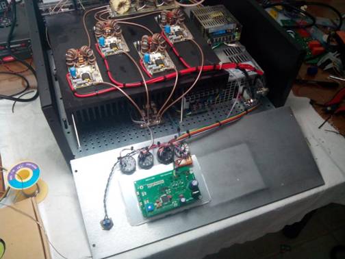
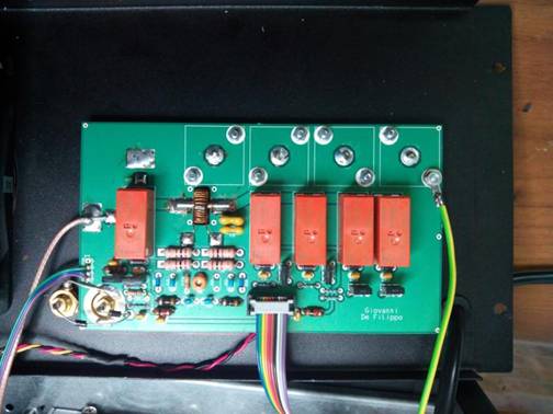
I
pallet EB104 non li ho buttati via ovviamente, con uno ho realizzato un
"piccolo" lineare da 500-600W (400W max in
10m), l'altro di scorta:
Per
l'alimentazione del "piccoletto" ho fatto una furbizia, ho utilizzato
alcuni grossi diodi in serie, così all'aumentare della corrente richiesta
aumenta la caduta di tensione ai capi di questi (circa 2,5V alla massima
corrente): questa è una bella protezione a costo zero, infatti, gli MRF150
(come tutti gli altri transistor) a tensioni di alimentazioni più basse sono
quasi indistruttibili, anche a ROS elevati...
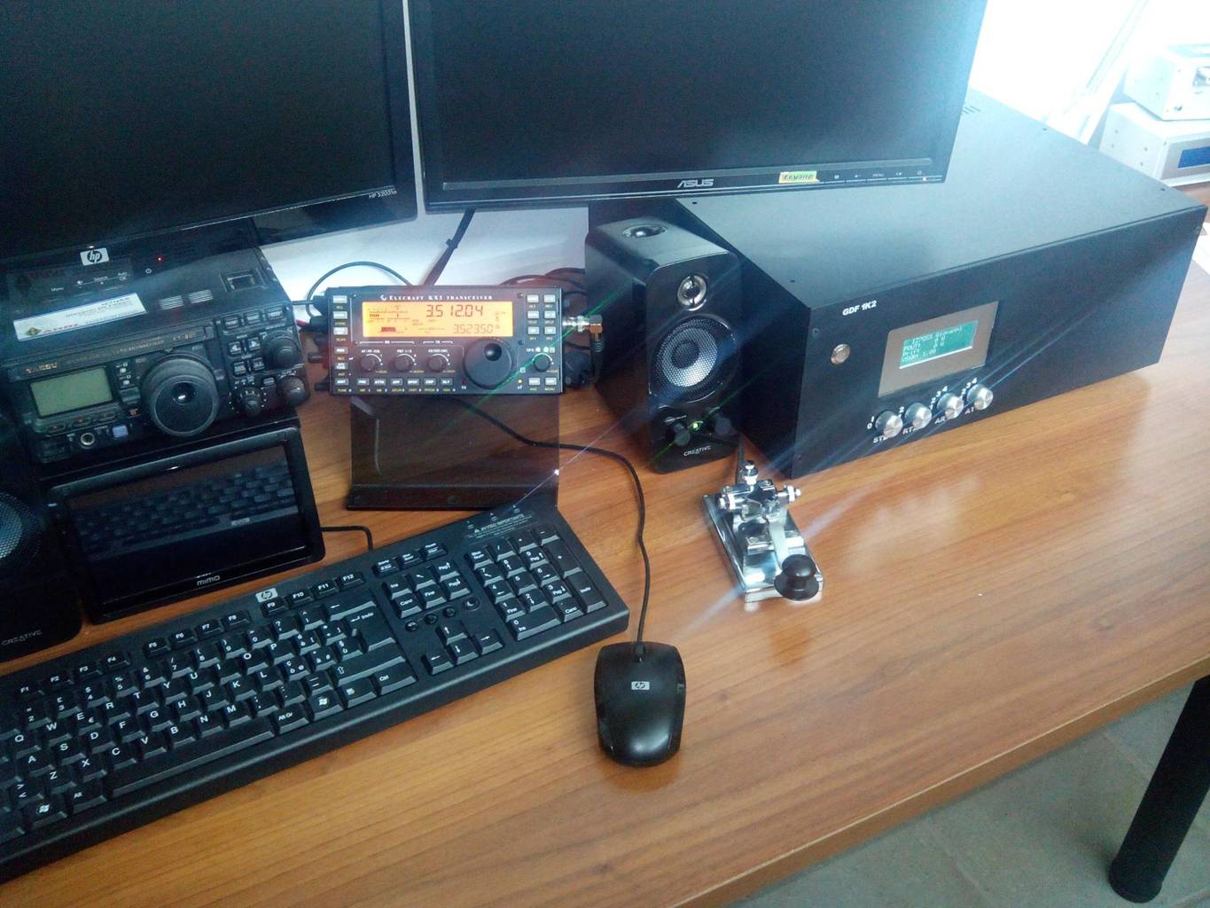
Una
panoramica nello shack:
![]() Giovanni
Giovanni