Iomega
Pcmcia card for USB Zip250
which is really
a Pcmcia to Atapi adapter
What
you will find on this page:
Personal opinion
on Iomega products in general
Details on the so called PCMCIA card for Zip USB
First of all I would like to share my personal opinions on
those Iomega products I have owned, and regretfully, repaired.
My first disappointment was a Ditto 2Gb that I purchased in 1996.
Apart from the hideous setup program that invites you to "relax"
while throwing on the screen a bunch of idiotic nonsense designed
by a couple of frustrated wanna-be artists, the unit stopped working
close enough to the expiration of the warranty. After having decided
to throw the anyway useless piece of machinery, I decided to open
it. Well, surprise, surprise, the cheapness of the design was
not limited to the installation software. The entire assembly
is held together by plastic tabs, and the leds are mounted on
the PCB with plastic strips acting like fiber optics shine their
light to the outside world. Certainly efficient on their side,
but awful to deal with if you have to open the darn trap.
The unit was literally ripping the tape off the reel, not sensing
the holes in the tape that announce the end of it. Connecting
a scope to the output of the sensor, I could see pulses when the
holes passed by. I first thought that the controller must have
gone bad, and I was about to junk the unit for the second time.
Instead I messed with the pull-up resistor that connects to the
photo-transistor in the sensor. I pulled the resistor off completely,
and replaced it with the series of a fixed resistor of half its
original value, plus a variable of the same value of the original.
By adjusting the variable resistor, the fronts of the pulses were
now cleaner and the levels more accurate for a digital input.
Since then the unit started working again. Having fixed it, this
is when I actually decided to throw it out because I was tired
of spending $20 a tape for deadly-slow backups.
Opening an internal ZIP100 produces the same feeling of cheapness.
Most everything is mounted on the PCB with plastic extensions.
The eject button alias led is so tight that when the front is
slightly pushed, it won't move enough anymore to actually work.
The whole frame is very light and bends very easily.
Now, the external model are instead... just as bad. After only
a couple of months that I carried a SCSI external in my computer
case, it rattles like a snake in heat. I must admit though, it
still works!
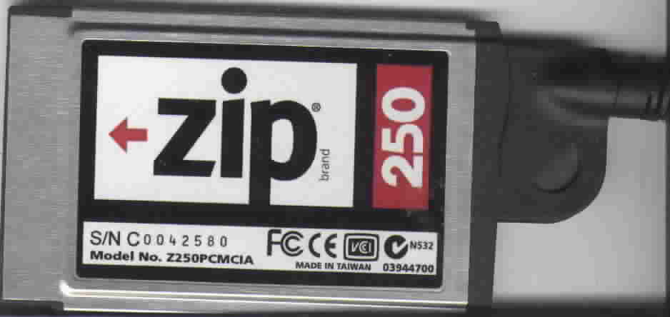
The so called PCMCIA card for zip250 USB
I was desperately looking for a PCMCIA to USB adapter that did
not require the 32-bit architecture known as Cardbus; just the
simple 16-bit standard PCMCIA. No luck for all I know and for
the reasonable amount of money such card should cost (considering
what's inside and what other similar cards are priced.)
So, I made the mistake to assume (watch your spelling) that the
PCMCIA adapter for the USB Zip-250 was indeed a PCMCIA to USB
card. The price was right, but the idea was very wrong. And so,
when I finally got the card in the mail, I found out with understandable
disappointment, that I hadn't solved my problem yet. By the way,
I'm still looking. The connector at the end of the cord is something
I have not been able to locate on this planet yet.
Maybe it's alien technology, but if anyone has a clue where to
find this bitch (no refs to female dogs), please let me know.
It's shaped exactly like the so-called Centronics connector, but
it has 50 pins and it is in general almost half its size both
in height and width. I cannot imagine they were made just for
Iomega, but I have searched the Internet forever without ever
coming across someone who sells or even lists them.
I looked up the Iomega website and, here is where you can laugh,
I thought I could gather some info from tech support. HA HA HA.
Instead I got a brush-off e-mail from some last-minute support-moron
who cannot even spell in English. The connector is as sacred as
the Coca-Cola recipe, and its connections are disclosed to God
himself only.
If I had a way to use it, the card would probably work greatly.
I mean, win98SE recognizes it just dandy like an ATAPI standard
interface. That was quite a surprise since I was expecting it
to be SCSI for two reasons: SCSI seems to be the interface of
choice by Iomega, and the 50 pins would also lead to SCSI. Even
the connector looks like a SCSI III, but it's not.
Much more helpful was Mr. H. Landis who pointed out that "All
the "standard" ATA/ATAPI connector are described in
Annex A of ATA/ATAPI-6 (get the PDF at http://www.t13.org)".
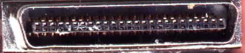
At this point I decided that it was time to get the knife out
once again, and dissect the critter. First I took off the molten
plastic case, then exposed the metal connector, removed most of
the white plastic with a heat gun, and got as far as this. Realizing
this was not going to help much, I noticed that out of the 50
pins, only 44 are used. Well, 44, that's a better number for an
ATAPI interface.
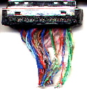
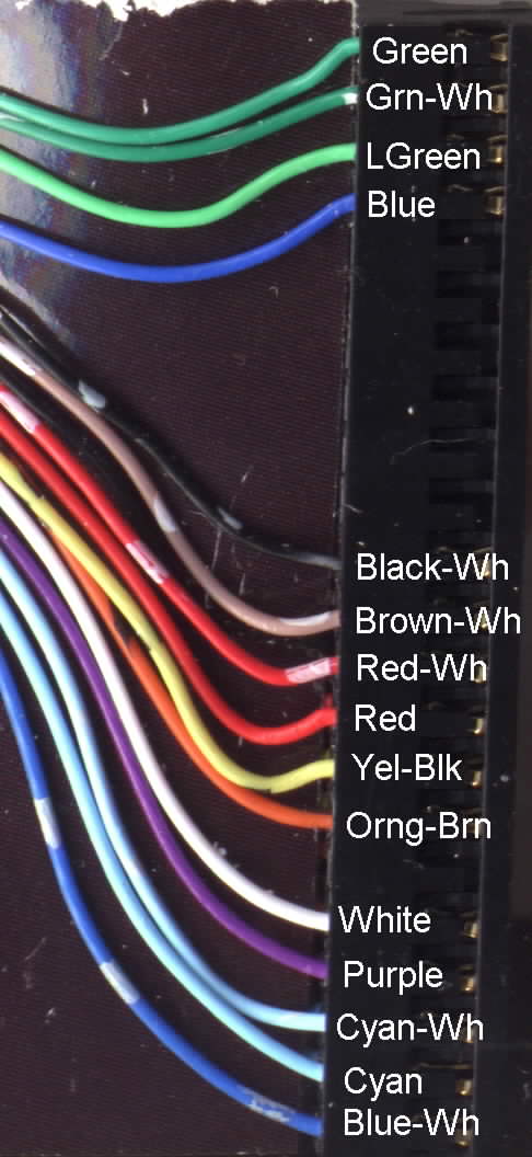
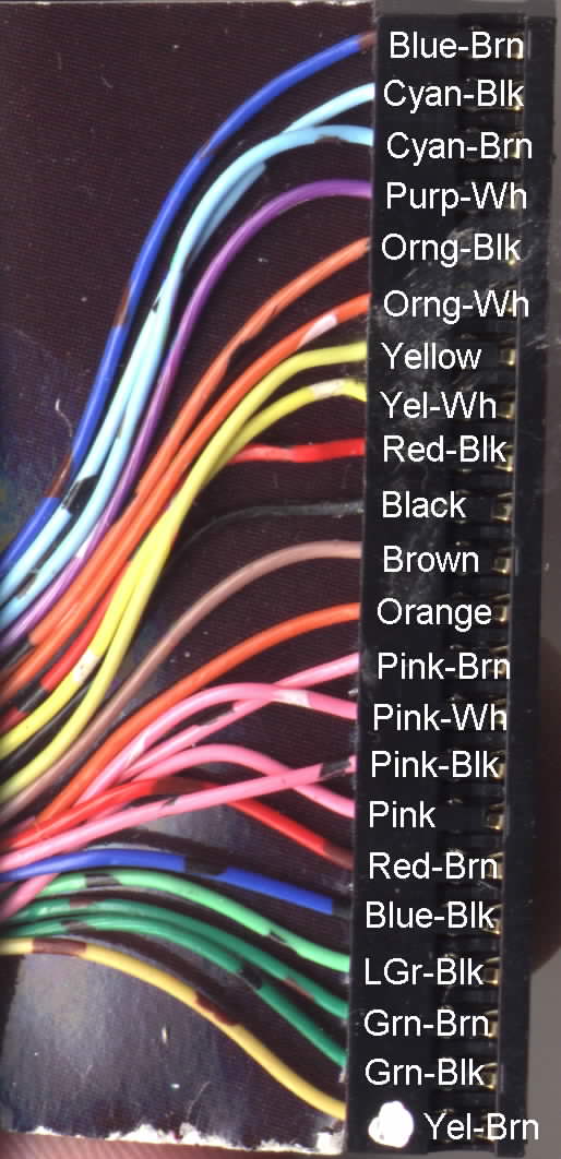
At this point I decided to open the card itself. So, with the
same Xacto knife I sliced through the sides and opened the case
completely. Here are better pictures of the wires at the top
and bottom of the connector inside the
card.
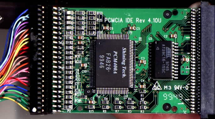
I got as far as noticing the 44pin edge connector that looks so
similar to a standard 44pin IDE interface on a 2.5" hard
drive, when I realized I don't really have a purpose for doing
what I'm doing, since I don't need to drive an external hard disc
through the PCMCIA slot.
Just for curiosity's sake, I would like to hear if anyone has
tried to connect this with anything, if anyone has ever heard
of this PCM400A chip, and if you know where to find a cheap PCMCIA
to USB card.
UPDATE
I can see that neither connectors matches the ATAPI 44 interface.
That's why my direct connection did not work. So, let's see how
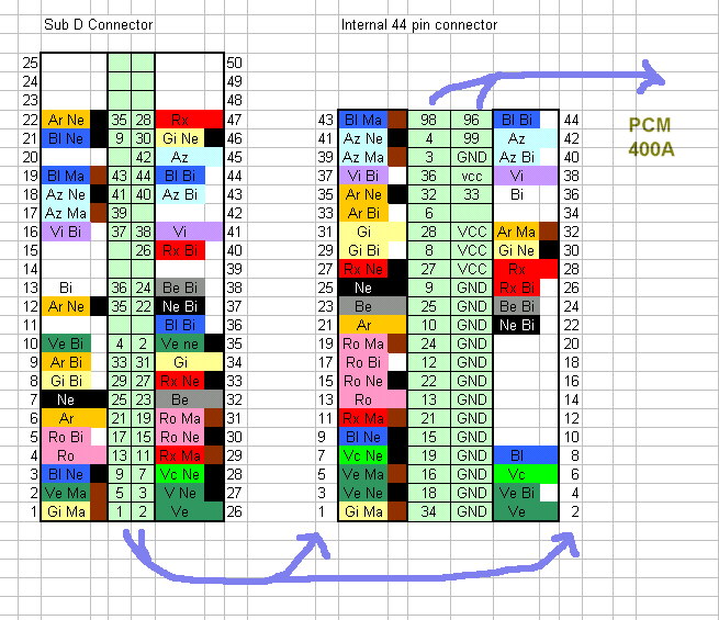
things are wired. I hope this can be one small little step further.
Starting from the SubD connector at the left (50 pins), each colored
wire connects to the 44 pin internal connector (to the pin number
shown in the left light green columns. This first diagram is probably
98% correct because some of the colors have melted before I could
really read them. At least this might give you some ideas.
The right table is 100% correct in the connections to the main
chip PCM400A. Each line connects to either VCC, GND or some pin
of the PCM chip.
Lines 35 and 36 connect directly to the PCM (Inputs to the PCM?)
Lines 3,4,36,96,98,99 connect to the PCM thourgh a 100ohm resistor
(Outputs of the PCM?)
Lines 6,8,9,10,12,13,15,16,18,19,21,22,24,25,27,28 connect to
the PCM through a 22 ohm resistor (16 bit IDE Data?)
Line 38 is pulled to VCC via 10kohm
click on the connectors to see a picture
Now it's a matter of seeing if this has any relation to a standard
IDE interface...
Also, the order of each line is still a mistery unless we find
a datasheet of the PCM400A.
Acknowledgments
Thanks to the totally useless customer service at Iomega that
considers all this such a secret.
Without their hostility I never would have started and shared
this project.
If you find this data useful, drop me a line at electrons@libero.it
;-)