What
you will find on this page:
Partial
Schematics.
No
More ID sent along with your codes.
Set
to Clean Unencrypted output.
The
Ultimate Expore-A-Cat
No More ID sent along
with your codes.
Ripping off the ID chip is the first and easiest part of this
project. Just desolder it or snip off its terminals. As an alternative,
close the 4 pairs of pads next to the ID Chip. Note the yellow
area where the 93C46 EEprom was removed to clear the wand's ID.
R1 to R4 were never mounted in the first place but can be replaced
with shorts.
Partial
Schematics
How do we go about understanding what's going on in this seemingly
hostile design?
Here is the diagram of the uC and direct connections.
Please note that I have only explored the PCB in order to determine
if it was possible to disable the encryption of data. I was looking
for pulled down input pins to the uC to be set high like in the
other versions, but I initially found no evidence that such an
option was ever considered.
This unit mounts a uC marked SyncMos SM2958, which is a clone of the 90C54
Please refer to the Datasheet of the 90c54 for the actual configuration of port 3, where pins 0,1,2 and 3 are used for general I/O instead of dedicated functions as shown in the box. They can be used as I/O or as specific peripherals according to the model and configuration of the chip.
What I found out by examining and testing the board is that at least 2 of the hardwired pins of the uC are polled and modify the behavior of the scanner.
Set
your cat to clean unencrypted output
|
First and best of all, P3.4 (pin 16) is the one responsible for setting the kitty to output clean unencrypted data. The numbering on
the PCB is actually NOT the standard way to indicate the pinout
of these chips. So, pin 16 is on the bottom side, last but one. |
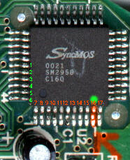 |
Second pin to play with is P3.5
(Pin 17). When this is not grounded (high) it sets the scanner
to output the same "clean" data, but according to a
different format that I have not yet explored. Looking with a
scope at the data sent to the keyboard, I believe the transmission
speed, frequency and style are very similar. I assume the coding
is just different, maybe raw binary form instead of ASCII. Let
me know if you have the patience to figure it out.
Perhaps this was done to interface directly to the RS232 or maybe
it-s a move toward USB. Beware that when this line is set to high,
the behavior of your keyboard will change dramatically. It may
not even respond until reset this pin to GND.
Input P1.4 (pin 6) seems to produce no visible changes when lifted from ground.
Changes made to these lines are not effective until you reset the uC by either unplugging the power/keyboard cord, or jump pin 10 to VCC (Reset).
If you have access to OrCad 3.10 (or newer), you can download the original schematic, Library (or plain text component definition)
Now, what I did, since I'm really tired of having to open and close this thing for each test, I decided to convert it to a flexible pet. How? Take a look at these:
 |
Here's kitty with the 3 pins lifted from the PCB, the top cover with a nice rectangular cut in the middle, and a set of 4 dip switches already wired as in this diagram. Here's the Orcad file of the diagram for the modification |
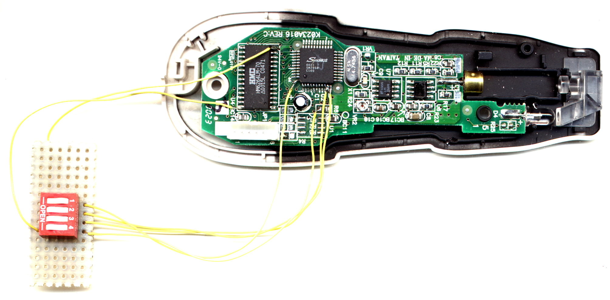 |
And here is how I got the switches connected to the 4 pins and power. For Vcc and GND I used pin 28 and 14 on the 6264 Ram Chip. Reset is pin 10 of the uC. |
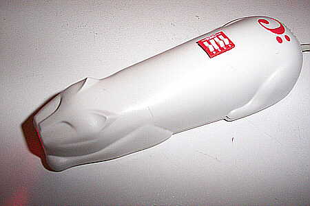
The Ultimate Explore-A-Cat: an extremely versatile kitty that purrs bar-codes like nothing else. The 4 switches on the top allow me to explore what happens by changing the input on those 3 mysterious inputs, while the fourth allows me to reset the uC without unplugging the cord.