Electronic guideline of a solar panel
The corrected guideline of a solar paddle towards the sun, essential thing in the operation of the solar concentrator is equally important also for the photovoltaic panels and for the panels for heating the water, because there is medium a doubling of the produced energy regarding the panels in fixed position.
Such guideline can be realized either by an analogic control of the electric motors premails to the movement then a digital control of the same ones, using an opportunely programmed microcontroller
The same microcontroller can find also the characteristics of operation of the panel in the time (caught up temperature, power produced electrical worker or heated water amount nell.unità of time) that he can then transmit periodically to personal a computer by means of a seriale connection for the visualization and the memorization of the data. Therefore, initially such guideline can be realized in analogic shape; subsequently it will convene to realize it in digital shape them or arranging the two methods.
Guideline by means of electronic control of the position of the sun
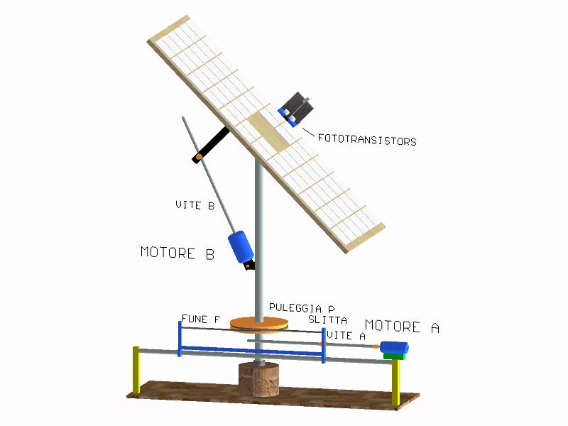
IT is based on a device composed from two perpendicular vertical fins between they that they subdivide the visual one in 4 equal parts.
To the base of each such part a fototransistor is placed that it finds the present brightness in that zone.
![]()
The value of the resistances R is from 47 KΩ or 100 KΩ ¼W; but it would be better to replace them with one resistance from 10K. in series to a potenziometro or trimmer from 100K., for regulating the tension better than exited, in conditions of equal lighting system of the 4 areas of the orientatore; the 4 fototransistor they are of type BPY 62 (you see symbols of the electronic members).
If the orientatore is not oriented correctly towards the sun, only one or more the two zones will be many illuminating; the others 2 or 3 zones will remain in shadow or conditions of smaller lighting system.
Such device goes connected loyal to the solar paddle so that when it will exactly turn out headed for the sun also the panel will be exposed in optimal way, receiving the light in perpendicular direction.
The tensions supplied from the circuits of the fototransistors, Va, Vb, Vc, Vd, inversely proporziona them to the brightness of each of the four zones come rispetivamente supplied all.ingresso of the two electronic circuits of control of the motor To and of the B motor; in everyone of these an operational amplifier connected to an opportune net electrical worker operates like an analogic calculating that realizes the following operation:
VmotoreA = K[(Va + Vc). (Vb + Vd) ] for the A motor
VmotoreB = K[(Va + Vb). (Vc + Vd) ] for the B motor
difference, amplified, come sended to a electrical net who realizes either the control on the intensity than on the sign of the result of such difference.
If the absolute value of the intensity exceeds a referement value of threshold it comes activated relè the 1 that supplies to feeding the circuit actuator of power costutuito from rele the 2, connected to the controlled motor (A or B).
Once fed, the control loop of the sign of the result of analogic computation it will activate or not the rele 2, that it realizes a polarity exchange of the feeding tension of the motor, that will rotate in a sense if relè the 2 remains not activated, in opposite sense if relè the 2 will be activated.
In this way the feed to the single electric motor will be activated only when it will be necessary to revise the panel guideline and removed just after, diminishing the energy necessary to the control that possibly must be a small fractionof the generated energy from the panel.
return to the constructive characteristics