
Electronic control loops
Electronic Control loop of the A motor
Electronic control loop of the B motor
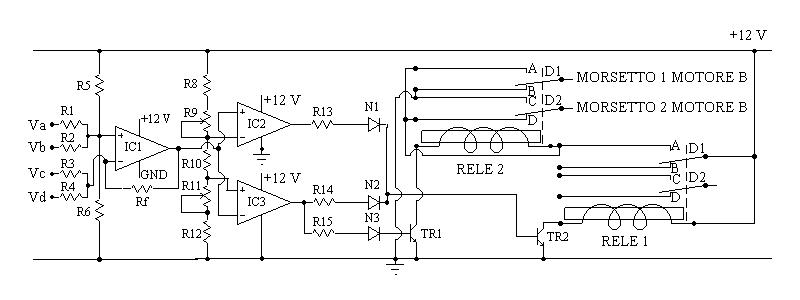
IC1, IC2, IC3 are 3 of the 4 operational amplifiers presents in integrated circuit LM324, that it has the particularitity of being able to be fed with a single voltage of feeding (the operational amplifiers of usual need of a double feeding voltage, to es. +12V and -12V).
Therefore clip Vcc of the integrated LM324 goes connected to +12 V; clip GND (ground or earth) goes connected to the pole negative of the local power source or the battery to 12V.
(Sees symbols of the electronic members).
TR1, TR2 are of transistors BC107 if the activation current of everyone of the relè does not exceed 0.1 - 0,2 Ampere (100 to milliampere or 200 to milliampere); if advanced they will have to be replaced with transistors of type "darlington" NPN, es. TIP127.
N1, N2, N3 are of the normal diode valves rectifiers to the silicon, to es. 1N4007.
(See symbols of the electronic members).
From the analysis of first part of the two circuits it turns out that, placing R1=R2=R3=R4=R5=R6 and Rf=1/2 R1, the voltage of escape from the first integrated circuit is expressed from the relation:
Voa = 0,5[(Va + Vc) - (Vb + Vd) ] + 6 Volt for the control loop of the A motor
Vob = 0,5[(Va + Vb) - (Vc + Vd) ] + 6 Volt for the control loop of the B motor
Therefore can be placed the resistances R1, R2, R3, R4, R5, R6 = 220 K Ω and 100+10 Rf = KΩ
Remaining two operational amplifiers IC2 and IC3, with to the resistances R8, R10, R12 and to the potenziometers or trimmers R9 and R11 determine either the sensibility of the control loop or the sense of spin of the single electric motor.
In fact the configuration of the voltage divider constituted from R8, R9, R10, R11, R12 determines one voltage Vsup = 6 + x Volt to the income - or negative of operational amplifier IC2 and one voltage Vinf = 6 - y Volt to positive income or + of the operational amplifier IC3; i values of x and y depend on the regulation of potenziometers R9 and R11.
We suppose Vsup = 6.1 Volt and Vinf = 5.9 Volt.
When the result of the algebrica sum of the voltages Va, Vb, Vc and Vd according to the brought back relations exceed 6.1 Volt, income + of IC2 will turn out to a greater voltage of the income - and the voltage of escape of such amplifier will be nearly equal to +12 Volt; at the same time the income - of IC3 it will turn out to a greater voltage of income +, connected to Vinf, therefore prevailing the sign - the IC3 escape will have one nearly equal voltage to 0 Volt;
therefore transistor TR2 through IC2 but not TR1 will be activated; consequently it will come activated relè the 1, that it feeds also the electric motor, but not relè the 2 and the corresponding motor will turn in a sense (as an example hour).
If instead the result of the algebrica sum of the voltages Va, Vb, Vc, Vd Volt is below the 5,9 Volt, income + of IC2 will turn out to an inferior voltage of that present to the income - (Vsup) and the voltage of escape of such amplifier will nearly turn out equal to 0 Volt; at the same time the income - of IC3 it will turn out to an inferior voltage to that present to income + (Vinf), therefore, prevailing sign + the IC3 escape will be to one nearly equal voltage to +12 Volt; therefore IC2 will not activate no transistor but IC3 will activate either the transistor TR1 or the transistor TR2, that they will activate respective either the relè 2 or the relè 1; therefore the correspondent electric motor will be fed but, being be activated also relè the 2 the polarity of the feeding will turn out inverted, and the motor will turn in inverse sense (as an example in counter-clockwise sense).
Finally, in the hypothesis that the algebrica sum result of the voltages Va, Vb, Vc, Vd be comprised between the 5,9 Volt and the 6.1 Volt, that is
5.9 Volt < Voa < 6.1 Volt
or
5.9 Volt < Vob < 6.1 Volt
either to the income of amplifier IC2 or to the income of amplifier IC3 will prevail the sign - and the escape of both will turn out to a voltage nearly equal to 0 Volt; nobody of two transistors TR1 and TR2 will be to
activated and therefore not even relè 1 and 2; the panel will remain in the position caught up until when the minimal threshold of activation of such circuits newly is not exceeded, saving electric power.
Care the values of the resistances, R8=R12=1 KΩ; R10=470Ω; R9 and R11 potenziometers or trimmers of 10 KΩ; R13=R14=R15 = 10 KΩ
The relè 1 and 2 could also be of the type miniaturized; relè the 2 with at least two shunters, relè the 1 also with a single shunter.
For the electric motors it is better to use of the demultiplied motors, as an example of the screwdriver portable; if their voltage of feeding is inferior to 12 V opportune resistance will be necessary to put in series one electrical worker; or to adapt two motors for wind-screen wiper for the cars, availables for few euros from a dismantler of cars; of usual they do not absorb more than 1 ampere everyone.
For greater details to write to
symbols of the electronic components
return to the constructive characteristics