|
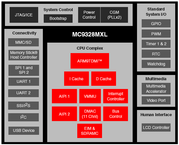
ARM920T Microprocessor Core The MC9328MXL uses the ARM920T microprocessor
core which has the following features:
 |
. 200 MHz maximum processing speed |
|
. 16K instruction cache and 16K data cache |
|
. ARM9 high performance 32-bit RISC engine |
|
. Thumb® 16-bit compressed instruction set for a leading
level of code density |
|
. EmbeddedICE. JTAG software debug |
|
. 100-percent user code binary compatibility with ARM7TDMI®
processors |
|
. ARM9TDMI® core, including integrated caches, write buffers,
and bus interface units, provides CPU-cache transparency |
|
. Advanced Microcontroller Bus Architecture (AMBA.)
system-on-chip multi-master bus interface |
|
. Flexible CPU and bus clocking relationships including
asynchronous, synchronous, and single-clock configurations |
|
. Cache locking to support mixed loads of real-time and user
applications |
|
. Virtual Memory Management Unit (VMMU) |
|
|
|
AHB to IP Bus Interfaces (AIPIs) The MC9328MXL AIPIs provide a communication
interface between the high-speed AHB bus and a lower-speed IP bus for slow
slave peripherals.
|
|
|
External Interface Module (EIM)
The MC9328MXL EIM features:
|
. Up to six chip selects for external devices, each with 16
Mbyte of address space (chip selects for ROM support a maximum of 32 Mbyte
of address space) |
|
. Programmable protection, port size, and wait states for
each chip select |
|
. Internal/external boot ROM selection |
|
. Selectable bus watchdog counter |
|
. Burst support for external AMD. or Intel® flash with
32-bit data path |
|
. Interrupt controller to handle a maximum of 63 interrupt
sources |
|
. Vectored interrupt capability with prioritization for 16
sources |
|
. Supports DTACK function in the CS5 |
|
|
|
SDRAM Controller (SDRAMC) The MC9328MXL SDRAMC features:
|
. Supports 4 banks of 64-, 128-, or 256-Mbit synchronous
DRAMs |
|
. Includes 2 independent chip-selects |
|
. Up to 64 Mbyte per chip-select |
|
. Up to four banks simultaneously active per chip-select |
|
. JEDEC standard pinout and operation |
|
. Supports Micron SyncFlash® SDRAM-interface burst flash
memory |
|
. Boot capability from CSD1 |
|
. Supports burst reads of word (32-bit) data types |
|
. PC100 compliant interface |
|
. 100 MHz system clock achievable with .-8. option PC100
compliant memories |
|
. single and fixed-length (8-word) word access
|
|
. Typical access time of 8-1-1-1 at 100 MHz |
|
. Software configurable bus width, row and column sizes, and
delays for differing system requirements |
|
. Built in auto-refresh timer and state machine |
|
. Hardware supported self-refresh entry and exit which keeps
data valid during system reset and low-power modes |
|
. Auto-powerdown (clock suspend) timer |
|
|
|
Clock Generation Module (CGM) and Power Control Module.
The MC9328MXL CGM and Power Control
Module features:
|
. Digital phase-locked loops (PLLs) and clock controller for
all internal clocks generation |
|
. MCUPLL generates FCLK to the CPU from either a 32 kHz or
32.768 kHz |
|
. System PLL generates the system clock and the 48 MHz clock
for the USB from a 16 MHz or either a 32 kHz or 32.768 kHz |
|
. Support for three power modes for different power
consumption needs: run, doze, and stop |
|
|
|
Two Universal Asynchronous Receiver/Transmitters (UART 1
and UART 2)
The MC9328MXL UARTs
feature:
|
. Support for serial data transmit/receive operation: 7 or 8
data bits, 1 or 2 stop bits, and programmable parity (even, odd, or none) |
|
. Programmable baud rates up to 1.00 MHz |
|
. 32-byte FIFO on Tx and 32 half-word FIFO on Rx that
support autobaud |
|
. IrDA 1.0 support |
|
|
|
Two Serial Peripheral Interfaces (SPI)
The MC9328MXL SPIs feature:
|
. SPI 1 is master/slave configurable, SPI 2 is master only |
|
. Up to 16-bit programmable data transfer |
|
. 8 × 16 FIFO for both Tx and Rx data |
|
|
|
Two General-Purpose 32-Bit Counters/Timers
The MC9328MXL General-Purpose Counters/Timers
feature:
|
. Automatic interrupt generation |
|
. Programmable timer input/output pins |
|
. Input capture capability with programmable trigger edge |
|
. Output compare with programmable mode |
|
|
|
Watchdog Timer
The MC9328MXL Watchdog Timer
features:
|
. Programmable time out of 0.5 s to 64 s |
|
. Resolution of 0.5 s |
|
|
|
Real-Time Clock/Sampling Timer (RTC)
The MC9328MXL RTC features:
|
. 32.768 kHz or 32 kHz |
|
. Full clock features: seconds, minutes, hours, and days |
|
. Capable of counting up to 512 days |
|
. Minute countdown timer with interrupt |
|
. Programmable daily alarm with interrupt |
|
. Sampling timer with interrupt |
|
. Once-per-second, once-per-minute, once-per-hour, and
once-per-day interrupts |
|
. Interrupt generation for digitizer sampling or keyboard
debouncing |
|
|
|
LCD Controller (LCDC)
The MC9328MXL
LCDC features:
|
. Software programmable screen size (a maximum of 640 × 512
pixels) to support single (non-split) monochrome, color STN panels, and
color TFT panels |
|
. Support for 4 bpp (bits per pixel), 8 bpp, and 12 bpp for
passive color panels |
|
. Support for 4 bpp, 8 bpp, 12 bpp, and 16 bpp for TFT
panels |
|
. Up to 256 colors out of a palette of 4096 for 8 bpp |
|
. True 64K color for 16 bpp |
|
. In color STN mode, the maximum bit depth is 12 bpp |
|
. In BW mode, the maximum bit depth is 4 bpp |
|
. Up to 16 grey levels out of 16 palettes |
|
. Capable of directly driving popular LCD drivers from
manufacturers including Motorola, Sharp, Hitachi, and Toshiba |
|
. Support for data bus width for 12- or 16-bit TFT panels |
|
. Panel interface of 8-, 4-, and 2-bits, and a 1-bit wide
LCD panel data bus for monochrome panels |
|
. Direct interface to Sharp® 320 × 240 HR-TFT panel |
|
. Support for logical operation between color hardware
cursor and background |
|
. Uses system memory as display memory |
|
. LCD contrast control using 8-bit PWM |
|
. Support for self-refresh LCD modules |
|
. Hardware panning (soft horizontal scrolling) |
|
|
|
Pulse-Width Modulation (PWM) Module
The MC9328MXL PWM Module features:
|
. 4× 16 FIFO to minimize interrupt overhead |
|
. 16-bit resolution |
|
. Sound and melody generation |
|
|
|
Universal Serial Bus (USB) Device
The
MC9328MXL USB Device features:
|
. Compliant with Universal Serial Bus Specification,
revision 1.1 |
|
. Up to six logical endpoints.see Table 1 on page 7 |
|
. Support for isochronous communications pipes |
|
. Frame match interrupt feature notifies the user when a
specific USB frame occurs |
|
. For DMA access, the maximum packet size for the
isochronous endpoint is restricted by the FIFO size of the endpoint |
|
. For programmed I/O, isochronous data packets range from 0
bytes to 1023 bytes |
|
. Support for control, bulk, and interrupt pipes |
|
. Packet sizes are limited to 8, 16, 32, or 64 bytes |
|
. Maximum packet size depends on the FIFO size of the
endpoint |
|
. Support (via a register bit) for a remote wake-up feature |
|
. Full-speed (12 MHz) operation |
|
. Operation can be programmed for both bus-powered and
self-powered mode |
|
|
|
Multimedia Card and Secure Digital (MMC/SD) Host
Controller The MC9328MXL MMC/SD Host
Controller features:
|
. Compatible with the
MultiMediaCard System Specification
(SPI mode excluded), version 3.1 |
|
. Compatible to 1/4 bit with the SD Memory Card Specification
(SPI mode excluded), version 1.0 and SD
I/O Specification (SPI mode
excluded), version 1.0 with 1 or 4 channel(s) |
|
. Up to ten MMC cards and one SD are supported by standard (maximum
data rate with a maximum of ten cards) |
|
. Support for hot swappable operation |
|
. Support for data rates from 20 Mbps to 80 Mbps |
|
|
|
Memory Stick® Host Controller (MSHC) The MC9328MXL MSHC features:
|
. Integrated 8-byte (4-word) FIFO buffer for transmit and
receive |
|
. Integrated CRC circuit |
|
. Support for internal or external serial clock source |
|
. Integrated Serial Clock Divider |
|
. DMA support; DMA request condition is selectable based on
FIFO status |
|
. Automatic command execution when an interrupt from the
Memory Stick is detected (can be toggled on/off) |
|
. RDY time-out period set by the number of serial clock
cycles |
|
. Interrupt output to the ARM920T core when a time-out
occurs |
|
. Two integrated general-purpose input pins for detecting
Memory Stick insertion/extraction |
|
. 16-bit host bus access (byte access not supported) |
|
|
|
Direct Memory Access Controller (DMAC) The MC9328MXL DMAC features:
|
. 11 channels to support linear memory, 2D memory, FIFO, and
End-of-Burst Enable FIFO for both source and destination |
|
. Support for 8-, 16-, or 32-bit FIFO port size and memory
port size data transfer |
|
. Support for big-endian and little-endian |
|
. Configurable DMA burst length for each channel up to 16
words, 32 half-words, or 64 bytes |
|
. Bus utilization control for a channel that is not
triggered by DMA requests |
|
. Bulk data transfer complete or transfer error interrupts
provided to interrupt handler (and then to the core) |
|
. DMA burst time-out error terminates the DMA cycle when the
burst cannot be completed within a programmed timing period |
|
. Acknowledge signal provided to peripheral after DMA burst
is complete |
|
|
|
Synchronous Serial Interface and Inter-IC Sound (SSI/I2S)
Module The MC9328MXL SSI/I2S
Module features:
|
. Supports generic SSI interface for external audio chip or
interprocessor communication |
|
. Supports Philips standard Inter-IC Sound (I2S)
bus for external digital audio chip interface |
|
|
|
Inter-IC (I2C)
Bus Module The MC9328MXL I2C
Bus Module features:
|
. Support for Philips I2C-bus
standard for external digital control |
|
. Support for 3.3 V tolerant devices |
|
. Multiple-master operation |
|
. Software-programmable for 1 of 64 different serial clock
frequencies |
|
. Software-selectable acknowledge bit |
|
. Interrupt-driven, byte-by-byte data transfer |
|
. Arbitration-lost interrupt with automatic mode switching
from master to slave |
|
. Calling address identification interrupt |
|
. Start and stop signal generation and detection |
|
. Repeated START signal generation |
|
. Acknowledge bit generation and detection |
|
. Bus-busy detection |
|
|
|
Video Port The MC9328MXL video
port supports external CMOS sensor video data input. |
|
|
General-Purpose I/O (GPIO) Ports
The
MC9328MXL GPIO ports feature:
|
. Interrupt capability |
|
. 97 total I/O pins multiplexed with most dedicated
functions for pin efficiency |
|
|
|
Bootstrap Mode The MC9328MXL Bootstrap Mode features:
|
. Allows user to initialize system and download program or
data to system memory through UART |
|
. Accepts execution command to run program stored in system
memory |
|
. Supports memory/register read/write operation of
selectable data size of byte, half-word, or word |
|
. Provides a 32-byte instruction buffer for ARM920T core
vector table storage, instruction storage and execution |
|
|
|
Multimedia Accelerator (MMA) The MC9328MXL Multimedia Accelerator features:
|
. MAC for FIR and FFT operation.MP3 applications save 10% to
15% CPU MIPS |
|
. DCT/iDCT hardware accelerator.MPEG4 decode applications
save approximately 10% CPU MIPS |
|
|
|
Power Management Features The MC9328MXL provides the following power
management features:
|
. Programmable clock synthesizer using either a 32 kHz or
32.768 kHz crystal for full frequency control |
|
. Low-power stop capabilities |
|
. Modules that can be individually shut down |
|
. Lowest power mode control |
|
|
|
Operating Voltage Range The MC9328MXL operating voltages are as follows:
|
. I/O voltage.1.70 V to 2.0 V or 2.7 V to 3.3 V |
|
. Internal logic voltage.150 MHz: 1.70 V to 1.9 V; 200 MHz:
1.8 to 2.0V |
|
|
|
Packaging The
MC9328MXL features two packages:
|
. 256-pin MAPBGA package with 14 mm × 14 mm × 1.3 mm, 0.8 mm
ball pitch |
|
. 225-pin PBGA package with 13 mm × 13 mm, 0.8 mm ball pitch |
|
|