Legged Simulator Usage[2006.04.26] |
 |
|
All distances and positions are measured in meters, angles in radians. World reference frame is left hand. If your feets are the (0,0,0) location, Z points toward your head, X points in front of you and Y is on your right. All these settings can be changed in the USARBot.ini configuration file, however this is only a quick introduction so I'm not going into these details and I'll use the default settings.
Simulator usage is really very simple since it's control is based on human readable text strings. I suppose you already have installed the simulator package. The first thing to do is to start USARSim using this command from a shell:
where DM-spqrSoccer2006 is the soccer map. If your map has another name, use it instead of DM-spqrSoccer2006.
This is not the only way to start the simulator, but it's the simplest one. Before starting USARSim I recommend to play a bit with UT2004 to familiarize with its many settings.
 |
Once started, the UT client will listen for incoming TCP connections on port 3000. You can use any kind of software to connect, until it supports reading and writing of text strings. The best solution is to program an own robot controller, however, to make just some experiment, you can use the SimTestTool provided in the Windows distribution or even a simple telnet client. Once connected you receive the following "welcome" string:
NFO {Gametype BotDeathMatch} {Level DM-spqrSoccer2006} {TimeLimit 0}
Now you can send command strings and receive sensor readings (not available until you create a robot). To create a robot in the map use the following command:
INIT {ClassName RobotName}{Skin SkinName}{Location x,y,z}
The aforementioned INIT command can be used to create any kind of robot among those defined in USARSim. Remember to terminate any string you send to USARSim with "\r\n". To make a more practical example I will focus on the AIBO. In this case the INIT command become:
INIT {ClassName USARBot.ERS}{Skin [RED | BLUE]}{Location x,y,z}
Examples:
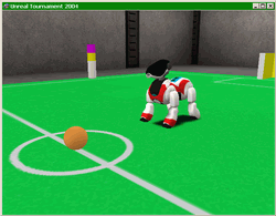
INIT {ClassName USARBot.ERS}{Skin RED}{Location -0.5,0,-0.3}
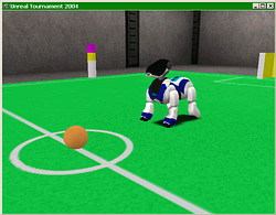
INIT {ClassName USARBot.ERS}{Skin BLUE}{Location -0.5,0,-0.3}
The above strings create a red or blue skinned AIBO in the Soccer2006 map placing it near the ball. Also this string is valid:
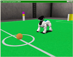
INIT {ClassName USARBot.ERS}{Location -0.5,0,-0.3}
 |
 |
 |
||
Red AIBO |
Blue AIBO |
AIBO with default skin |
If you don't specify any skin the default skin will be used. Since only AIBO currently support skins you can safely omit the {Skin SkinName} pair when creating other robots. To delete the robot simply disconnect.
Now you have create your first robot. Right after creation the robot will start to send sensory data. Typically it will send 5 readings per second (this value can be easily changed). The AIBO will send these strings (5 times per second):
The meaning of the STA string is explained in the USARSim manual, so please refer there. Let's analyze the other 3 strings.
SEN {Type IR} {Name IRN Range 0.5000} {Name IRF Range 1.5000} {Name EDG Range 0.2810}
SEN {Type Accel} {Name ACC} {Acceleration 0.00,0.00,0.00}
This string reports the instant acceleration in robot local reference (Z is up, X is front, Y is right).
SEN {Type Helper} {Name BHS}{Pos3D 0.0000,0.0000,0.0344}{Visible true}{Pos2D 104,179}{Radius 21}{Dist 0.4013}{Corona 2051}
This sensor helps AIBO in ball recognition process. Images rendered by the UT engine are too sharp, too perfect to be used for realistic image processing. That's why this sensor bypasses completely the image recognition stage providing direct information about the ball. This sensor provides the following informations:
The remaining parameters are only valid if the ball is visible, that is if the Visible flag is true.
 |
Image width and image height are fixed to 208 x 160, that is the AIBO ERS-7 camera resolution. You can change these values editing CameraXres and CameraYres variables in [USARBot.BallHSensor] section of the USARBot.ini config file.
 |
 |
 |
 |
 |
Corona parameter encodes visibility of 12 samples of the ball circumference. To each sample corresponds a bit in the generated code. So if the code is 64 only the sample n.6 is visible, if the code is 3 only samples 0 and 1 are visible, and so on.
 |
Legged robots can be easily controlled with a single command:
MULTIDRIVE {joint_1 value}{joint_2 value}{joint_3 value}...
Joint_n is the name of the joint to control, value is the desired joint angle. Joint names are robot specific, the following image refers to the AIBO joints configuration:
 |
AIBO joint names are RFA, RFB, LFA, HA... If you want for example to set RFA and LFA joint angles to 1 radian you'll send this command:
MULTIDRIVE {RFA 1}{LFA 1}
QRIO joints configuration is:
 |
QRIO joint names are RAA, LAC, RLA, LLD, HA... If you want for example to set RAA and RAB joint angles to 0.5 radian and LAA and LAB joint angles to 0.7 radian you'll send this command:
MULTIDRIVE {RAA 0.5}{RAB 0.5}{LAA 0.7}{LAB 0.7}
It's really that easy :-)
Joints motor speed, torque and other parameters can be edited in the USARBot.ini file, however they don't use a PID controller but a custom proportional control managed by the Karma engine itself.
I hope you successfully completed this quick tutorial. Basic simulator usage is really very simple, however, if you're willing to learn UnrealScript, you'll find that it's also very flexible and allows you to personalize everything, to add new robots, sensors, maps and even more.