IW3IPD 20m PSK31 QRP transmitter
SCHEMATICS
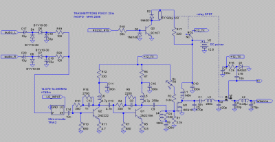
This is the schematic diagram of the transmitter. Values are indicated as they are in the prototype and in many cases parts can be exchanged with similar components. For example the relay coil is indicated as 5V because that part was available, and the 220 ohm resistor in series with the coil is good for making that specific relay work at 12V.
click on the picture for a larger version
The trimmer near the MOSFET sets the operating point for AB class. It should be initially set to the maximum resistance. Then the transmitter should be switched on without the LO signal and the power supply current measured. Finally, the resistance decreased until the current increases of more or less 60mA. During these operations a dummy load should be connected to the output (oscillations less likely to happen). If the current suddendly jumps to a high value (like 0.5A), there is probably self-oscillation. In this case look for unwanted coupling between stages.
It may seem strange that no variable capacitor is used. This is because I tuned the circuit using fixed parts. The most critical part is C2, which would deserve putting a 10-60pF variable capacitor in parallel with 390pF. C3, C4, C5, C9 are not particularly critical.
The diodes BYV10-30 used in the audio circuits are 30V, 1A schottky. Any similar diode is good, but they must be schottky with low conduction resistance, otherwise the distortion would become unacceptable due to the high voltage threshold and low circuit impedances.
The TFM-2 mixer can be replaced with many other types, provided that they support the 14MHz frequency on LO and RF and they work up to DC on the IF port.
The PIN diode on the receiver port (BA243) is not strictly necessary. I have used it because the relay isolation during transmission is relatively poor (the relay is not for RF) and the diode improves it a lot. Since it is not reverse-biased with a negative voltage during reception, it also worsens receiver IM performance, but this is true only for high quality receivers, not for my ATS909.
I have used several SMD components which are barely visible in the photographs on the main page. For example, the emitter resistors for the 2N2222 and 2N2219 are 0603 parts, giving a beneficial very short path to ground. As is shown in the following photograph, the emitter is attached to a small piece of PCB fixed to the base with thermal glue and the resistor forms a short bridge to ground:

Inductances:
L1: 4 turns, 1.2mm silver-plated wire, 10mm internal dia, 7mm length
L2: 10 turns, 1.2mm silver-plated wire, 10mm internal dia, 19mm length
L3: 6 turns, 1.2mm silver-plated wire, 10mm internal dia, 12mm length
L4: 8 turns, 1.2mm silver-plated wire, 10mm internal dia, 15mm length
I have some LtSpice simulation files available. I will reorganize and make them available soon.