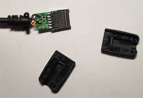
| Seguire passo per passo.
Follow step by step Aprire il connettore con un taglierino cercando di non danneggiare i fili Open the Kable socket with a cutter and pay attention to NOT damage or cut wires |
 |
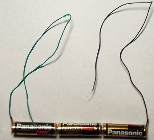
| Usare una batteria da 4,5 v o meglio 3
batterie da 1,5 stilo AA o AAA in serie con la giusta polarit�. Saldare ai
due estremi i fili. (Verde Positivo e NERO negativo della figura)
Use a 4,5 Volts battery, or better using using 3 x 1,5
Volts battery AA type in series (- + .. - + ... - + ) |
 |
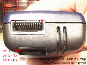
| WARNING Il cavo originale Siemens non consente di accedere al PIN e di attivare l'ignition che si ottiene premendo il tasto di accensione rosso. Usando la batteria si simula tale azione. C55 e M50 hanno differenti PINS. ATTENZIONE The Originale datakable CAN'T manage the "ignition" pin so with a external battiery is possible to "simulate" the RED button softly push using voltage of batteries. C55 and M50 have different PINS . BE CAREFUL! ------------------------------------------------------------------------------------------------------
PER C55 (Non valido per M50 e altri modelli inferiori
X35...) Per M50 and X35 e altre precedenti serie
For M50 and older series as X35
ERRORE il PIN POSITIVO E' il 4 e non il 3 |
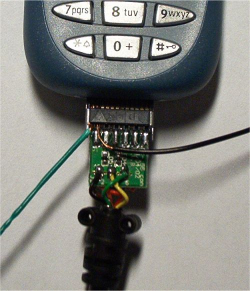 Esempio posizionamento fili per per C55 Example for C55 wires  |
| For original Procedure in GERMAN
ask me link. THANKS 1000 !! to LastActionHero (German) |
. |
HOW to get a datakable in Italy ???
Dove trovare un cavetto in Internet ?
- Gratis sul sito www.pitstopsiemens.it
L'unico problema � che � originale, e quindi niente procedura Early Bird.
Per cavi non originali:
www.zetabyte.com
http://www.alientech.it/zetabyte/zetabyte.htm
http://www.cavigsm.com/
http://www.phonia.it
C55 cable
In order to activate java and to read and to transfer data to the telephone we needed a cable, but it is not worth any cable, has to be a cable nonoriginal Siemens. A very common error is to buy the original cable of the Siemens mark and soon to verify with horror that does not serve to make the things that we wanted more. The Siemens C55 has a narrower connector, reason why the cable that we could use in the Siemens X25, X35, X45, X50, etc does not serve to us, we needed one new specific one for the C55. Basically are two options with respect to the cable of the C55, or to buy one specifically for him (very difficult to still find in Spain) or to modify the cable of the old models and to adapt it to the connector of the C55.
1� Option: to buy the cable by
Internet.
SEE FAQ
2�
Option: to modify the old cable (type X35- M50)
Necessary materials: the old cable, a tin soldering iron and one files. In order
to obtain our intention first we will have to file the connector of the cable
until it is left the sufficiently thin thing like so that it fits in the hollow
of the connector of the C55. Next we will have to disassemble to the cable by
the part of the connector and behavior to interchange its pins using the tin
soldering iron as much to desoldar as to return to weld. Here down I let the
scheme to know to you how to interchange them:
M50 CABLE and Scheme
This is a Siemens generic Pinout up to M50 model
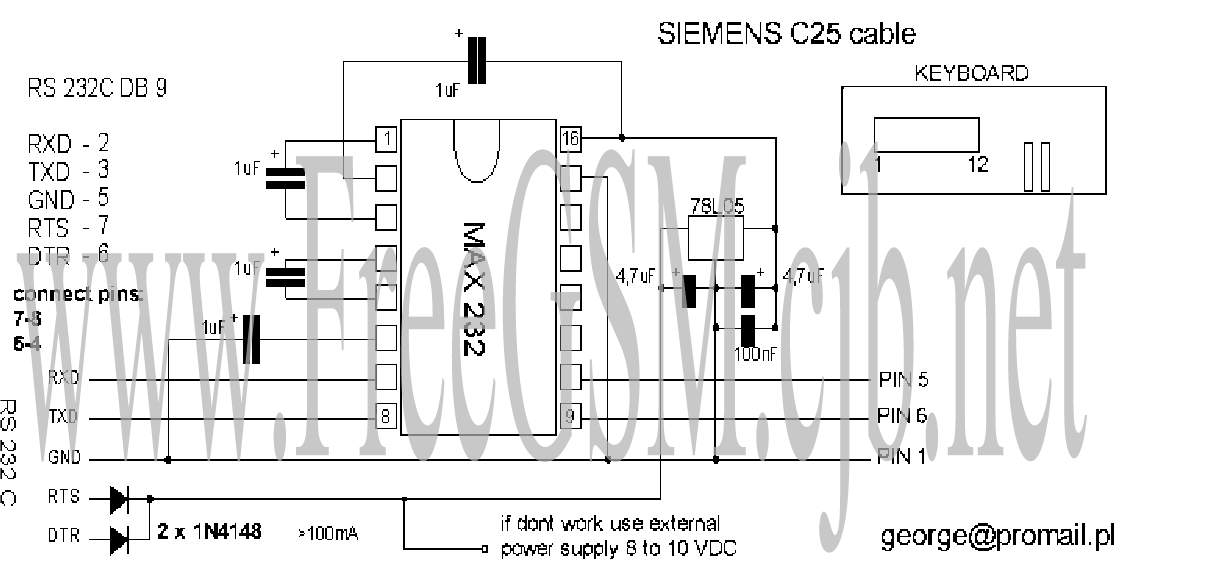
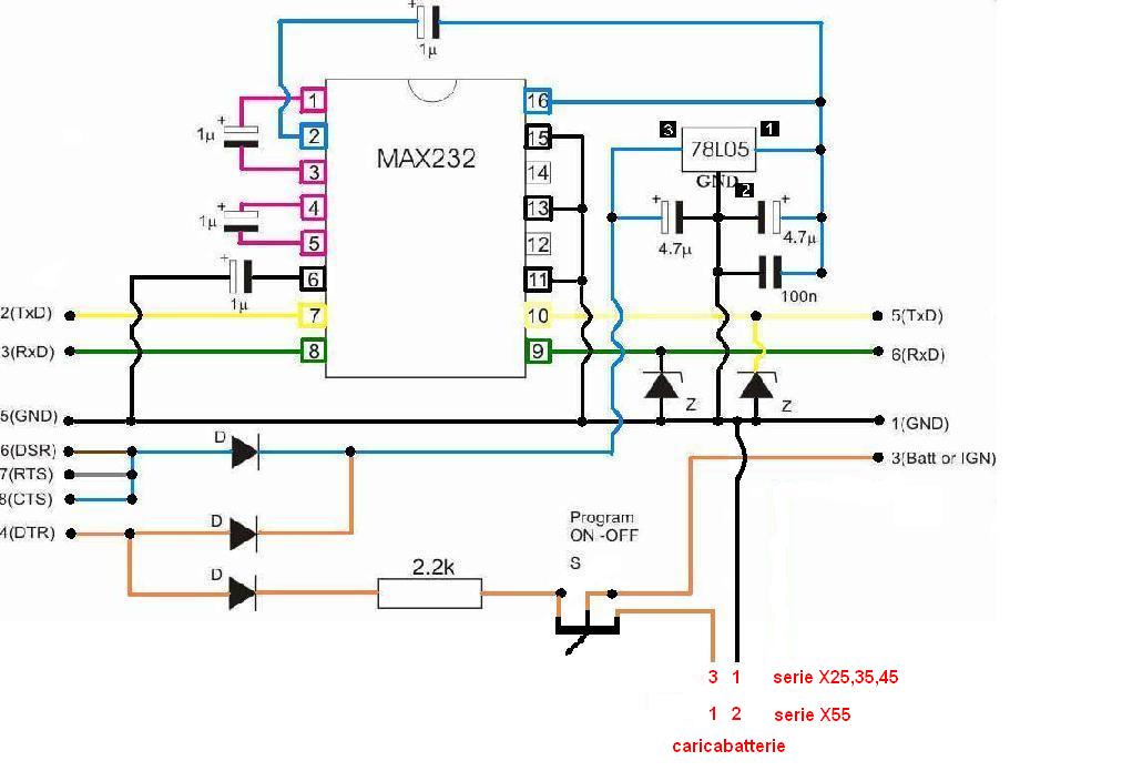
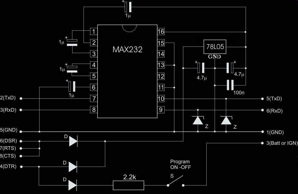
Electrical scheme for M50 Data Cable

Another electrical Scheme for M50 Data cable
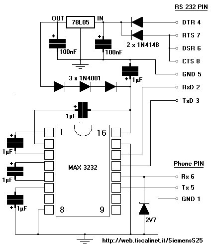
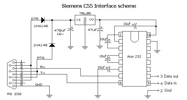
Schema for a C55 Siemens - Schema elettrico per Cavo C55 |
|