DESCRIPTION
Sailboat heel control device
TECHNICAL FIELD
A multi-hull or a single-hull sailboat comprising at least one sail-mast that moves to boat leeward-side in consequence of a wind force on the sails and/or of a crew action.
The side hulls of the multi-hull boat comprise each other a rod sliding secured to float-rod guides.
The leeward hull sinks in consequence of the sail-mast movement and/or of the crew action and thus the buoyancy caused by the sinking opposes the heeling moment caused by the wind force on the sail-mast.
Whereby, when the sail-mast moves to boat leeward-side, the force exerted on the windward shroud by the sail-mast and producing the heeling moment is transmitted to the leeward hull to sink it.
The single-hull sailboat comprises two shaped and dimensioned floats positioned on the two sides of the hull and these floats comprise each other a rod, said rod sliding secured to float-rod guides. The leeward float sinking in the single-hull sailboat causes the same results of the leeward hull sinking in the multi-hull sailboat.
According to the present invention, the crew can manually regulate a length of the windward shroud for performing any required sail-mast position and any required sinking of the leeward hull or float.
BACKGROUND ART
Generally, a sailboat is heeling in consequence of a wind pressure on the sails and this heel can be partially or completely counteracted by the crew windward movement.
The IT Patent n. 01285406 (03 June 1998), the WO 97/00804 (9 January 1997) and the US Patent n. 5,947,045 (Sep.7, 1999) report a device that counteracts a heeling moment and a drift of a multi-hull or of a single hull sailboat, caused by a wind force on the sail, without any crew action.
That device sets the sail-mast position and the boat heel only in consequence of the wind force on the sail surface.
Therefore, that device comprises at least one sail-mast moving transversally in respect to the hull, in consequence of the wind force.
In addition, the side hulls of the multi-hull boat comprise each other a rod, sliding secured to float-rod guides.
The leeward-side hull sinks in consequence of the sail-mast movement, thus the buoyancy caused by the sinking opposes the heeling moment caused the wind force on the sail-mast.
Whereby, when the sail mast moves to sailboat leeward-side, the force exerted on the windward shroud by the sail-mast and producing a heeling moment is transmitted to the leeward hull to sink it.
Similarly, the single-hull sailboat comprises two shaped and dimensioned floats positioned on the two sides of the hull and these floats have each other a rod, sliding secured to float-rod guides.
The leeward float sinking acts in the single-hull sailboat as the leeward hull sinking in the multi-hull sailboat, thus obtaining the same results.
The present invention extends the results of said former invention, so that the crew manually sets any required boat condition. In order to perform these results, the crew acts a specific device installed in the connecting line between the sail-mast and the lateral hulls or the floats.
DISCLOSURE OF INVENTION
This invention concerns an improvement of the former invention shown in the aforesaid documents IT Patent n. 01285406 (03 June 1998), WO 97/00804 (9 January 1997) and US Patent n. 5,947,045 (Sep.7, 1999).
According to this improvement, the sail-mast position and the sailboat heel depend on the crew action, and not only on the wind force on the sail surface.
The crew acts a device installed in the connecting line between the sail-mast and the floats or the side hulls for setting a sail-mast position and a sailboat heel.
The description and the drawing are referred to a boat with a single sail-mast, but the invention is applicable also to a boat with more than one sail-mast, as skilled people clearly understand.
BRIEF DESCRIPTION OF DRAWING
Figures from 1 to 22 show the invention carried out in two different modes and installed both in a single-hull and in a multi-hull sailboat.
The wind blows from the right side of the reader in all figures that show the boat when it is sailing.
BEST MODES FOR CARRYING OUT THE INVENTION
First mode
The figures 1 to 13 show a first mode for carrying out the invention on a multi-hull sailboat. To make figure easy to be understood, fig. 1 shows the invented device with reference only to the right shroud.
Figures 2 to 7 show in detail the various arrangements of the invention, in consequence of the crew settings.
The invented device (figures 1 and 2) comprises the hoist P3 connected to the winch V1 through the cable F5, the holes B1 and B3 at the hoist ends and the holes B5 and B7 on the beam H. These holes are used by the crew for fastening trough keys the hoist ends to the beam.
The invented device is installed between the cable F1, that is an extension of the shroud S1, and the cable F3, that pushes down the rod A1 of the hull L1.
The crew controls the device to perform many different sailboat conditions:
Figures 10 and 11 show the same position of the boat, of the sail-mast T and of the leeward hull L1, but these figures are referred to two completely different behaviors of the boat.
According to figures 4 and 10, the crew can set a different sail-mast tilt, acting the winch V1.
According to figures 5 and 11, the crew can set a different heel of the whole boat, likewise acting the winch V1.
Moreover, according to figures 4 and 10 an increase of the wind force causes a bigger sail-mast tilt and a deeper leeward hull sinking. According to figures 5 and 11, an increase of the wind force causes a heel of the whole boat.
Figure 14 shows a single-hull sailboat comprising the invented device. To make figure easy to be understood, the device is installed only on the right shroud. This figure clearly shows that the device is equal to the device installed on the multi-hull sailboat (fig. 1). Therefore, the device details are the same details shown in figures 2 to 7 and we can carry out exactly the same remarks aforesaid for the multi-hull boat.
Second mode
Figures 15 to 21 show a second mode for carrying out the invention on a multi-hull boat.
Figure 15 is the front-view of a multi-hull boat, when it is sailing. To make figure easy to be understood, this figure comprises the invented device installed only on the right shroud, and shows a section of the left hull.
Figures 16 to 21 show in detail the various arrangements of the invention, in consequence of the crew settings.
The invented device comprises (fig.15 and detail of fig.17) the pump W1 and the check-valve J1, that are connected through the pipes U and the valves J to the hydraulic cylinders Z1 and Z3. The device comprises in addition the tank M1.
Figures 16 to 21 show the pipe U3, the compensation vessel C1 and the valves J9 and J11. To make figure easy to be understood, these components are omitted in fig. 15. The valve J9 is closed during the sailing and the crew opens it when the boat is in a rest situation or for filling the vessel C1 through the pump W1, closing all the other valves. Likewise, the valve J11 is normally closed and the crew opens it to charge or discharge some air in the vessel C1, for regulating vessel pressure.
The crew acts the pump W1, the valves J1, J3 and J7 to perform the same sailboat sailing trims performed in the first mode to carry out the invention:
The remarks that we made on figures 10 and 11 in the first mode of carrying out the invention are fully applicable in the second mode.
Figure 22 shows a single hull sailboat comprising the invented device carried out in the second mode. To make figure easy to be understood, the device is installed only on the right shroud. This figure clearly shows that the device is equal to the device installed on the multi-hull sailboat (fig. 15). Therefore, the device details are the same details shown in figures 16 to 21 and we can carry out exactly the same remarks aforesaid for the multi-hull boat.
INDUSTRIAL APPLICABILITY
The invention reported in the above mentioned documents IT Patent n. 01285406 (03 June 1998), WO 97/00804 (9 January 1997) and US Patent n. 5,947,045 (Sep.7, 1999) increased the sail-boat safety, the crew and passenger comfort, the sail efficiency and the hull hydrodynamic performances according to the design parameters. The crew couldn�t make a change in these parameters during the sailing.
The present invention makes the crew able to optimize easily and quickly the boat performances during the sailing, according to the instantaneous occurrences.
A sailboat can be generally used for many purposes. For example for an easy family cruise or, instead, for a sailing race. Besides, the sailboat can be sailed from a skilled or an unskilled crew. Moreover, the sailboat can afford many different sailing situations and it can have very different loads.
The crew can use the present invention for achieving the best boat trim in any time and in any situation. In other words, this invention makes the boat suitable for many purposes, so that we achieve with a single sailboat the same performances that we can achieve with many sailboats lacking in the invention:
The present invention, as described above, makes a single sailboat able to achieve the performances of more traditional sailboats. A single sailboat comprising the present invention can be used for many purposes.
We remark that the invention is carried out using normally used components.
These components had very long tests on the sailboats (winches and hoists in the first mode, pumps and hydraulic cylinders in the second mode for carrying out the invention). Therefore, the device is fully reliable.
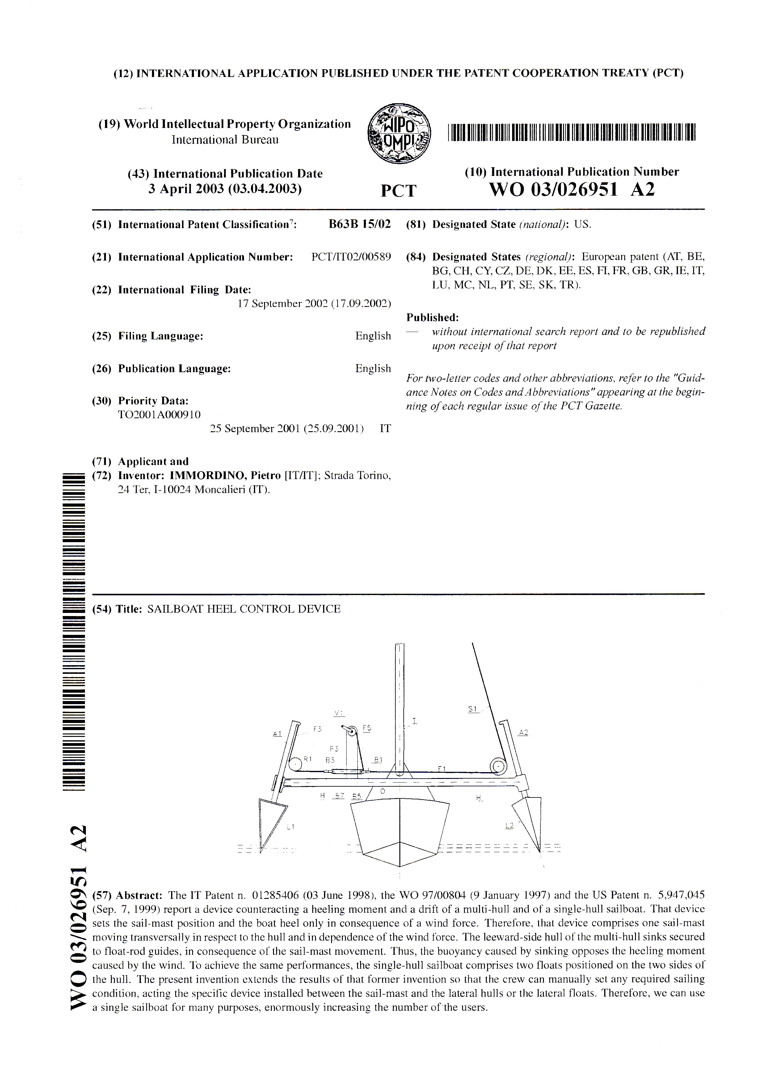
The crew can quickly and easily act the device. In the first mode for carrying out the invention, the crew acts at the most a single winch and fits/unfits one or two keys in their holes. In the second mode for carrying out the invention, the crew acts a single pump and at the most three or four valves.
Therefore, we can design a sailboat light (without ballast), reliable in all the sailing situations, and, in consequence of a chosen setting, quick and/or safe and/or easy to sail and/or comfortable.
At last, we can assert that the present invention completely modifies the traditional sailing ways. We can use a single sailboat for many purposes, enormously increasing the number of the users.
CLAIMS
at least two hulls, said hulls having at least one sail-mast moving transversally in respect to said hulls and in dependence of a wind direction, and said hulls having a leeward-side and a windward-side;
at least two float-rod guides secured to said sail-mast by a beam;
at least two rods, said rods secured to said hulls and sliding secured to said float-rod guides on ends of said beam;
at least one windward shroud secured to said sail-mast at one end and said leeward-side rod at the other end, and said windward shroud being passed through a system of blocks and pulleys for transmitting a force exerted on said sail-mast from said windward shroud to said leeward-side rod;
at least one leeward shroud secured to said sail-mast at one end and said windward-side rod at the other end, and said leeward shroud being passed through a system of blocks and pulleys for transmitting a force exerted on said sail-mast from said leeward shroud to said windward-side rod;
whereby when said sail mast moves to said hulls leeward side, said force exerted on said sail-mast and producing a heeling moment is transmitted to said leeward rod pushing said leeward-side hull down, causing a sinking depending on the strength of said force, thus a buoyancy caused by sinking of said leeward-side hull opposes the heeling moment caused by said force on said sail-mast characterized in that:
said windward shroud is passed through at least one system of hoists and winches;
said leeward shroud is passed through at least one system of hoists and winches;
whereby said system of hoists and winches of said windward shroud is used by the crew for making a change in the length of said windward shroud, causing a change in the tilt of said sail-mast in consequence of a crew action.
a length of said windward shroud comprised between said sail-mast and said system of hoists and winches incorporates at least one key, said key fastening said length to said beam securing said float-rod guides to said sail-mast, so stopping said sail-mast in a fixed position;
whereby said system of hoist and winches of said windward shroud is used by the crew for transmitting a force to said leeward rod pushing said leeward hull down, causing a sinking depending on a crew action, thus a buoyancy caused by the sinking of said leeward hull opposes a heeling moment of said sailboat.
a length of said windward shroud comprised between said leeward rod and said system of hoists and winches incorporates at least one key, said key fastening said length to said beam securing said float-rod guides to said sail-mast, so stopping said leeward hull in a fixed position;
whereby said system of hoist and winches is used by the crew for transmitting a force to said sail-mast, making a change in the tilt of said sail-mast in consequence of a crew action.
at least one key fastens each end of said system of hoist and winches of said windward shroud to at least one bar;
whereby a length of said windward shroud comprised into said system of hoist and winches is fixed, thus a position of said sail-mast and a sinking of said leeward hull depends only on a force on said sail-mast.
at least one key fastens each end of said systems of hoists and winches of said windward shroud and of said leeward shroud to said beam securing that float-rod guides to said sail-mast;
whereby said sail-mast and said side hulls are stopped in a fixed position, thus the whole sailboat heels stiffly connected to said sail-mast.
at least two floats, positioned on the two sides of the hull, said hull having at least one sail-mast moving transversally in respect to said hull and in dependence of a wind direction, and said hull having a leeward-side and a windward-side;
at least one float-rod guide secured to said hull on each said windward and leeward-sides;
at least two rods, said rods secured to said floats and sliding secured to said float-rod guides;
at least one windward shroud secured to said sail-mast at one end and said leeward-side rod at the other end, and said windward shroud being passed through a system of blocks and pulleys for transmitting a force exerted on said sail-mast from said windward shroud to said leeward-side rod;
at least one leeward shroud secured to said sail-mast at one end and said windward-side rod at the other end, and said leeward shroud being passed through a system of blocks and pulleys for transmitting a force exerted on said sail-mast from said leeward shroud to said windward-side rod;
whereby when said sail mast moves to said hull leeward side, said force exerted on said sail-mast and producing a heeling moment is transmitted to said leeward rod pushing said leeward-side float down, causing a sinking depending on the strength of said force, thus a buoyancy caused by sinking of said leeward-side float opposes the heeling moment caused by said force on said sail-mast characterized in that:
said windward shroud is passed through at least one system of hoists and winches;
said leeward shroud is passed through at least one system of hoists and winches;
whereby said system of hoists and winches of said windward shroud is used by the crew for making a change in the length of said windward shroud, causing a change in the tilt of said sail-mast in consequence of a crew action.
a length of said windward shrouds comprised between said sail-mast and said system of hoists and winches incorporates at least one key, said key fastening said length to said hull, stopping said sail-mast in a fixed position;
whereby said system of hoist and winches of said windward shroud is used by the crew for transmitting a force to said side leeward rod pushing said leeward float down, causing a sinking depending on a crew action, thus a buoyancy caused by the sinking of said leeward float opposes a heeling moment of said sailboat.
a length of said windward shroud comprised between said leeward rod and said system of hoist and winches incorporates at least one key, said key fastening said length to said hull, stopping said side float in a fixed position;
whereby said system of hoist and winches is used by the crew for transmitting a force to said sail mast, causing a change in the tilt of said sail-mast in consequence of a crew action.
at least one key fastens each end of said system of hoist and winches of said windward shroud to at least one bar;
whereby a length of said windward shroud comprised into said system of hoist and winches is fixed, thus a position of said sail-mast and a sinking of said leeward float depends only on a force on said sail-mast.
at least one key fastens each end of said systems of hoists and winches of said windward shroud and of said leeward shroud to said hull;
whereby said sail-mast and said side floats are stopped in a fixed position, thus the whole sailboat heels stiffly connected to said sail-mast.


