
![]()
![]()
![]()
![]()
![]()
MY SLOPERS ANTENNAS FOR 80 AND 160 MT.
(clik here for to look design)
As for all long-wire antennas also these that I am going to describe are
very simple but incredibly efficient.
I actually discovered this type of antenna owing to some problems with
available space around my house. But at the end they came out to be
absolutely superior to any dipole I tried before.
Considering only reception we have two extra s points and, if you
consider the bands we are talking about, this is not insignificant.
After building the first sloper, for 80 mt., I discovered that it was
working so well that I decided to produce a two-band sloper for 80 and 160.
The first version of sloper was the classical type: 20 mt. of wire
attached directly to my 15 mt. tower coming down as a slope of about 35-40°
according to your possibility.
My garden border are rather close to the house.Anyway everything was
working perfectly.
Therefore I decided to experiment a trap for 80 mt using a 2 mm. wire,
40 spires around a diam. of 50 mm. with a spacing of 3 mm. I also added
a capacitorof 100 pf 10 kv.
I tuned up for 8o mt and I then added 12 mt of wire to make the whole
thing available for 160 mt. band.
All this long wire was going around the house on the fence with
neighbours but that did not create any problem and it was not a danger
for anybody. I had this antenna installedfor over an year and my
contactson the air, on both bands, were actually rather interesting,
mainly on 16o mt.:W,J6,JX,OY,8P,VE,EA8,EU and always within the power
limits allowed in Italy.
Later on I decided to install a second sloper but in another direction:
from South-West to North-East.
But here I had a problem with my house borders and had to cut my antenna
to be no longer that 17,50 mt.!
With the help of my good friend IK4GLV I built up a sloper antenna with
a tuning system at its head consisting in a coil with 40 spires of wire
onto a 50 mm core and with a 3 mm spacing ( the same as for the 80 mt.
trap). The 17,50 mt. of wire were brought into tune with two 100Pf
capacitors then we added a coil at the end using 78 spires of 1 mm.
copper wire on a 100 mm core.
Also a little tail was added in order to reach the 160 mt. tuning
available.
The result: I stayed within my borders and was able to work on 80 and
160 mt but..... There is alway a "but" in our life.
The new antenna was crossing over another dipole and the result was not
perfect. My garden is not as large as a football lawn!
I could work well all the European countries but that was all.
Therefore I changed my sloping system by flinging 32 mt of wire over the
yards of two of my neighbours!
The same sloper I had on the South-West side, now was also on North-East.
Only very slight TV interference but everything was then working
perfectly I carried out important contacts with JY,JA,W,A6,EZ,JW with
only 100 Watts. Not too bad. The problem anyway was all that wire out
of my borders. I had told my neighbours that it was only an experiment.
Therefore, here we are: a 80/160 mt sloper with only 17,50 of wire
with linear load and capacitive hat.
SLOPER 80/160 with only 17,50 mt.
Do you remember the antenna with linear load for 30 and 40 mt. I
published on CQ magazine in July 1998 ?
Since this antenna gave me great satisfaction I extended my experiments
to the bands of 80 and 160 mt.
The necessary calculations were the same as for the other antenna and
also this time they proved to be right. Theory and practice: all o.k.
As a matter of fact, after calculating the length of the sloper and of
the load, and after assemblig everything, I installed the antenna and
made the necessary checking of the resonance on the frequency of my
nterest. But let's go step by step:
1) First of all why a sloper?
In my case because it is much shorter that the two dipoles I had on and
also it has far less problems of installation.
Last but not least it came out to be an exceptional antenna for DXing.
Everybody knows that a quarter-wave for 80 mt. is approx. 20 mt. long
but not all the hams have space enough to deploy such an extent of wire.
Therefore many prefer to install a commercial dipole for 40 and 80 mt.
because it is 20 mt.long in all. And here we are again.
I cut 5 mt of wire off the quarter-wave and put on a linear load.
The most important step was how to build all this and also installation
was not so simple since you have to know what to do and how to do it.
2) All I did was to try to eliminate, as far as possible, all the dif-
ficulties and tried also to solve my problems also using the materials
that I already had int he barn.
If the sloper is made with a wire, as in my case, one must pay attention
so as to keep the linear load in shape.
I built it with 8/10 mm. aluminium rods. I also used the same insulators
that space the load elements by passing in their centre the wire that
make up the sloper.
3) As far as feeding is concerned I used the RG213 cable with the sheath
into my tower and the core connected to the antenna.
The feeding point must be very strong since it has to hold the entire
antenna weight. I therefore suggest to fix the sloper on to a 10x20 cm.
PVC plate.
This must have a 5mm thickness. Drill the necessary holes for fixing
the PL plug and the R213 cable.
4)Fixing and tuning the 80 mt. freq. is quite a problem but don't give
up because your satisfaction will be great!
At this stage wehave 80and 160 upon only 17,50 mt. of antenna.
I will respect the boundaries with my neighbours.
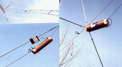
After tuning my sloper on the 80 mt., I added a trap by using 40 spires
of 2mm. wire around a 50 mm.core: I finally added a high power 100 pf
10kv capacitor.
In order to have the trap working on the wole 80 mt. band I welded 5
rings on the first 5 spires that will allow me to move the capacitor
up or down in order to tune any part of the band according to my requi-
rements. This solution is very useful also for the fine tuning of 80 mt.
5) Here we are now with the tuning of 160 mt.I have wound 27 mt. of
1.5 enamelled wire around a 100mm. diam.core. Very close spires and at
the end I put a capacitive hat on made by 3 radiators made with a 10mm.
diam, 80 cm.long aluminium pipe. I suggest to us two pipes of different
diam.,one into the other in order to fine-tune the 160 mt.band.
As a matter of fact you will tune by changing the length of the radia-
tors. Between the trap and the coil let 1.20mt. of wire.
This antenna seems difficult to make but it is more difficult to explain
than to actually make it.
I hope that the attached pictures will help on the job.
SHORT SLOPER 80/160: LAST CHAPTER.
The story is not over. Further experiments and tests have proved that
my sloper needs no balancing system. I had anyways to make some change
on the length of the feeding cable that I discovered should be as long
as the whole antenna: therefore around 18 mt. more or less.
After this modification on the final load the performance in transmission
was a little increased, not a lot but something, yes.
Then I worked on the distance between the linear load and the 8 mt, trap.
I found the best result in 1.2 mt. I started from 2 mt.
At this stage I started with the installation of 3 short slopers,
identical, opened as a fan and 120° of distance between each other, with
3 identical feeding cables that go directly into the shack on 5 ways
manual switch (this also is self made in the barn, of course).
The ground plane of my sloper is made with 4 radiants of 40 mt. wound
around a 30mm PVC core buried in the ground for traffic problems.
The whole lot is connected to the cable coming down from my tower for
grounding.
After all this I have the following results:
1) Each sloper is independent from all the others.
2) During tuning up I found basolutely no interference of any type
3) You cover the whole 360° horizon (good for DX).
4) When one sloper is in use, the other work as reflectors.
5) And, finally, everything is within my boundaries!!!!
I have also made up another similar sloper but alla made with wire,
instead of aluminium pipes for the linear load, and performances are the
same excpet that it is much lighter in weight.
At the end of the story my opinion is that I would suggest the "all
wire" version to anybody who will feel like to follow my steps.
All mechanical problems connected with this version have then to be
faced according to the maker's experience.
With the antenna system I have just described I have faced the CQWW CW
160 in reply to all contesters and, except some Central Anerican countries
that did not hear me, I have made all the contacts I was interested in:
I must confess the difficulty connected with the lack of power on this
band but my satisfaction was great.
As you will notice I have tried not to be too much technical but as much
practical as I could.
The only technical aspect is the calculation of the linear load.
The rest is only goodwill!
The spirit I have tried to put in my stories is not that of trying to
emulate Marconi (Excuse me Guglielmo) but to stimulate other Hams in
"home -brewing" in order to save it from extinction and to give a sense
to the Old Men's spirit that is not that of sitting in front of a radio
or of a keyboad.
Think it over, dear Old Men and try sometimes.
I remain, as always, at full disposal for any further information.
IK4DCS - Franco