* * * * Ground plane for 30/40 mt * * * * IK4DCS

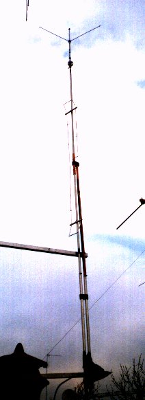
VERTICAL 30/40 MT, SHORT BUT NOT TOO !

After a period spent studying what type of antenna could be better to install, in the middle of the jungle of wires that I find myself on
roof, the band of 30 meters, I thought it was a vertical fit.
The reasons for this choice, they were directed to an antenna I could offer some possibility in DX, but for practical impossibility to mount a directive since the mast and already occupied by a non-compact, but extremely functional, delta loops 7 elements for 10/15/20 mt.
Both the lattice that the post dedicated to support the antennas of 2 meters.
6 meters high respectively roof, so I will forecast a Another problem: the total height of the vertical could be well, otherwise I would hit the overlying directives.
Hence the need for an antenna short, but it could make it anyway.
And I decided that I would make a vertical for 30, with load linear.

Then I began to make calculations, find tubes and screws, insulators and screwdrivers, hacksaw the inevitable and omnipresent drill.
But the most important to me, and those who have already been contacted , first me, had had experience with this type of antenna: IK4GLV.
So, thanks to some of his advice and suggestions, I began construction of the antenna in question.
But, who knows 'why', I continued building during works well 2 radiators: Clearly the achievement of a dipole.
Well, that is, a finished work sizes were well above what actually I wanted, even as semi-dipole!
No, no, I removed everything and started again with the original project.
Well, I put in a vertical semi-dipole and I realize that already  begin to rationalize.
The calibration makes me even shorten the antenna about 50 cm, and it is well!

Then, just think, you could groped to make it dual band 30/40.
Adding a trap, then a tip ...... no, too long !

But in the meantime, everything was fine: ringing in the bands want, more stable than acceptable and reports received quite flattering. And to further shorten the tip, what wear? a capacitive load and you're done.
Another shortening of about 1 m and the total response of the antenna very good, I guess.
Then, another problem, I could not encroach on the roof of the neighbor with the ties to support the antenna, so I created the condition of being brackets using the self-supporting insulating material and extending the arm is not a PVC pipe with radiation for at least 1.50 mt.
Now the mechanical part: of course, as builder, I have all material found in my "personal" storage compound about a hundred kilograms. of aluminum tubes of all sizes and diameters of all conceivable accumulated in 20 years activities radioamateur as well as all the insulating material, so diameters going to provide below will be subject to change depending on the availability of material by individuals.

The antenna is divided into 4 parts: radial, radiator with linear load,  trap tip with capacitive load.
The radial, in my case, are 6 (3 for 30 and 3 for 40) long physically the physical height of the band to be covered and not grounded,
electrically. In the power point I have interposed a baloon 1:1, home made of course, for the conjugation of the impedance and the groove must be at least an inclination of about 90 ° and at least high one meter from the roof, or floor, without being in tension, but simply
slowly, and held in place with the ends.
Radiator: the first part of the radiator is long 2.30 mt with a diameter of  outer 30 mm, and here the problems begin to merge the second part maintaining a certain rigidity of the radiator structure.
I have overcome the obstacle by inserting, between the two tubes, a round Teflon equal to the diameter of the pipe for about 20 cm by taking part spacing between them of about 15 cm and externally by combining two sections of the radiator with a PVC pipe inside diameter appropriate thickness 3 mm., 30 cm long.
At both ends 'internal radiator, will be' connected load linear will be a fixed size, the load is long the measure of
shortening (30%) of the fourth wave -20% of the fourth wave.
In practice, if we reduce the physical antenna, 30% ( Only advised not to exceed this threshold ) will have approximately 2.20 meters in
shortening this measure and we add 20% on the quarter-wave physical (Mt 1, 50) then the linear load will be 'long about 3.70 meters.
This measure sets the keep, and the load will be forged with the sections of aluminum tube diam. 8 where folding is necessary
and studying the systems more appropriate to the achievement of insulators which will serve to hold the cargo along the element.
The spacing between the two long parts of the load is of about 15 cm on side and 5 cm on the inside. It would be better to proceed with the wire aluminum disk with a diameter of 3 mm, but it may be more complicated to hold firm, although much more light!

The top of the radiator for the 30, is 1.60 meters long, but here is better to use two different diameters and leave the last part controlled
for calibration.
Without calibration, we apply a trap for 30 meters tip : my trap is RG58 coaxial cable (5 coils diam. 60 in air with appendix for calibration), taking as a model to text "antennas Volume 2 "by Nerio P. Blacks. 223.

Caution: Do not diameters, but only the electrical connection. Who has a good trap-meter will definitely more facilitated.

Above the trap, there goes the tip that we must combine with the trap in order to make the structure the more rigid as possible.
I acted in the same manner used for the linear load.
The tip for the 40 meters and 'found to be 70 cm long, but we recommend take a tip adjustable with two different diameter telescope and
bottom 45 cm long.
Between the two diameters of the tip will put the load capacitance (ex radial of glorious GP for 2 mt in QRT ) 3 groove 50 cm long each.
The load is no longer positioned as' removed and the calibration of 40 m. takes place on the top of the tip.
Eventually my antenna and 'found to be 5 meters long due to the calibration and the elongation of the linear load of about a 3% increase .
To ensure that the antenna thus formed does not need braces I extended my arm mass next to the radiator for about mt. 1 and then I inserted a diameter of 30 mm. PVC 3 mm thick. long 1.50 meters that allowed me to get to the island load
Linear and here I hooked with another suitable insulator.
Structure is not too stiff, but quite robust. And since this area where I live and 'beat at least 2 times a year by tornadoes, next year I will be able to provide even the mechanical result effective.
I think it is extremely simple dish, the more complicated explain that to do, so join my writing some design and some pictures to make more clear the job done.
I'd say everything last thing, from tests done on shore and final installation in the roof, there was a different response on the 40 m
stationary and increased a bit , while 30 were inhibited the presence of other poles and wires that sounded right in 30 causing many problems of RF interference of any kind.
So should install the most far as possible from any thing that could create this kind of incidents. The 40 were systems work on radials, and not on the radiator, precisely on inclination of them: then there was also a saint to give me a hand, I do not know, but I do know that generally "a self-built antenna that goes to someone else is house will not go never! " the famous Murphy's Law.
Good job to those who will want to challenge themselves in the enterprise home brew of GP 30/40.

IK4DCS